7. Interrupt controller
A96G140/A96G148/A96A148 User’s manual
70
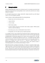
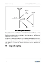
Figure 18. Interrupt Sequence Flow
7.5
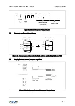
Effective timing after controlling interrupt bit
Case A in figure 17 shows the effective time after controlling Interrupt Enable Registers (IE, IE1, IE2,
and IE3).
Saves PC value in order to continue
process again after executing ISR
IE.EA Flag
0
1
Program Counter low Byte
SP
SP + 1
M (SP)
(PCL)
2
Program Counter high Byte
SP
SP + 1
M (SP)
(PCH)
3
Interrupt Vector Address occurrence
(Interrupt Vector Address)
4
ISR (Interrupt Service Routine) move, execute
5
Return from ISR
RETI
6
Program Counter high Byte recovery
(PCH)
M (SP), SP
SP - 1
7
Main Program execution
10
Program Counter low Byte recovery
(PCL)
M (SP), SP
SP - 1
8
IE.EA Flag
1
9


