16. USART 2
A96G140/A96G148/A96A148 User’s manual
198
16.6
Parity bit
Parity bit is calculated by doing an exclusive-or of all the data bits. If odd parity is used, the result of the
exclusive-or is inverted. The parity bit is located between St + bits and first stop bit of a serial frame.
P
even
= D
n-1
^ … ^ D
3
^ D
2
^ D
1
^ D
0
^ 0
P
odd
= D
n-1
^ … ^ D
3
^ D
2
^ D
1
^ D
0
^ 1
P
even
: Parity bit using even parity
P
odd
: Parity bit using odd parity
D
n
: Data bit n of the character
16.7
USART2 transmitter
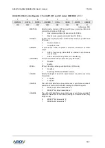
USART2 Transmitter is enabled by setting the TXE bit in UCTRL1 register. When the Transmitter is
enabled, normal port operation of TXD2 pin is overridden by serial output pin of the USART2. Baud rate,
operation mode and frame format must be setup once before doing any transmissions.
If synchronous or SPI operation is used, a clock on the XCK pin will be overridden and used as a
transmission clock. If USART2 operates in SPI mode, SS2 pin is used as SS2 input pin in slave mode
or can be configured as SS2 output pin in master mode. This can be done by setting SPISS bit in
UCTRL3 register.
16.7.1
Sending Tx data
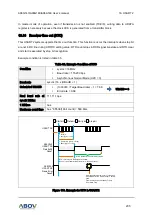
A data transmission is initiated by loading a transmit buffer (UDATA register I/O location) with data to
be transmitted. The data written in the transmit buffer is moved to a shift register when the shift register
is ready to send a new frame. The shift register is loaded with new data if it is in idle state or immediately
after the last stop bit of the previous frame is transmitted.
When the shift register is loaded with new data, it will transfer one complete frame at the settings of
control registers. If 9-bit characters are used in asynchronous or synchronous operation mode
(USIZE[2:0] = 7), the ninth bit must be written to the TX8 bit in UCTRL3 register before loading a transmit
buffer (UDATA register).
16.7.2
Transmitter flag and interrupt
The USART2 Transmitter has 2 flags which indicate its state. One is USART2 Data Register Empty
(UDRE) and the other is Transmit Complete (TXC). Both flags can be used as interrupt sources.
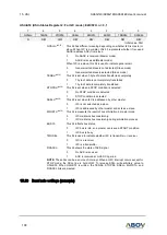
UDRE flag indicates whether the transmit buffer is ready to be loaded with new data. This bit is set
when the transmit buffer is empty and cleared when the transmit buffer contains transmission data
which has not yet been moved into the shift register. And also this flag can be cleared by writing ‘0’ to


