Appendix
A96G140/A96G148/A96A148 User’s manual
262
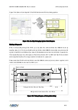
Figure 140 shows a timing diagram of each bit based on state of the DSCL clock and the DSDA data.
Similar to I2C signal, the DSDA data is allowed to change when the
DSCL is ‘L’. If the data changes
when the
DSCL is ‘H’, the change means ‘START’ or ‘STOP’.
Figure 140. Bit Transfer on Serial Bus
Figure 141. Start and Stop Conditions
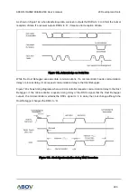
During the OCD communication, each data byte is transferred in accompany with a parity bit. When
data is transferred in succession, a receiver returns the acknowledge bit to inform that it received.


