15. USI
A96G140/A96G148/A96A148 User’s manual
190
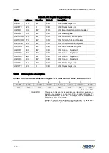
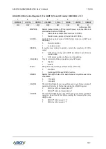
USInST2 (USIn Status Register 2: For I2C mode): E2H/F2H, n = 0, 1
7
6
5
4
3
2
1
0
GCALLn
TENDn
STOPDn
SSELn
MLOSTn
BUSYn
TMODEn
RXACKn
R
R/W
R/W
R/W
R/W
R/W
R/W
R/W
Initial value: 00H
GCALLn
(NOTE)
This bit has different meaning depending on whether I2C is master or
slave. When I2C is a master, this bit represents whether it received
AACK (address ACK) from slave.
0
No AACK is received (Master mode)
1
AACK is received (Master mode)
When I2C is a slave, this bit is used to indicate general call.
0
General call address is not detected (Slave mode)
1
General call address is detected (Slave mode)
TENDn
(NOTE)
This bit is set when 1-byte of data is transferred completely
0
1 byte of data is not completely transferred
1
1 byte of data is completely transferred
STOPDn
(NOTE)
This bit is set when a STOP condition is detected.
0
No STOP condition is detected
1
STOP condition is detected
SSELn
(NOTE)
This bit is set when I2C is addressed by other master.
0
I2C is not selected as a slave
1
I2C is addressed by other master and acts as a slave
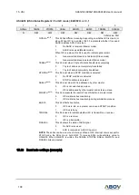
MLOSTn
(NOTE)
This bit represents the result of bus arbitration in master mode.
0
I2C maintains bus mastership
1
I2C maintains bus mastership during arbitration process
BUSYn
This bit reflects bus status.
0
I2C bus is idle, so a master can issue a START condition
1
I2C bus is busy
TMODEn
This bit is used to indicate whether I2C is transmitter or receiver.
0
I2C is a receiver
1
I2C is a transmitter
RXACKn
This bit shows the state of ACK signal
0
No ACK is received
1
ACK is received at ninth SCL period
NOTE:
These bits can be a source of interrupt. When an I2C interrupt occurs except for
STOP mode, the SCLn line is hold LOW. To release SCLn, write arbitrary value to
USInST2. When USInST2 is written, the TENDn, STOPDn, SSELn, MLOSTn, and
RXACKn bits are cleared.
15.23
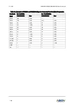
Baud rate settings (example)


