15. USI
A96G140/A96G148/A96A148 User’s manual
158
15
USI (USART + SPI + I2C)
USI stands for the combination of USART, SPI and I2C. A96G140/A96G148/A96A148 has two USI
function blocks, USI0 and USI1, which are identical to each other functionally. Each USI block consists
of USI control registers 1/2/3/4, USI status registers 1/2, USI baud-rate generation register, USI data
register, USI SDA hold time register, USI SCL high period register, USI SCL low period register, and
USI slave address register (USInCR1, USInCR2, USInCR3, USInCR4, USInST1, USInST2, USInBD,
USInDR, USInSDHR, USInS
CHR, USInSCLR, USInSAR). The ‘n’ means ‘0’ or ‘1’.
USI operates in one of the following modes selected by USIn selection bits (USInMS[1:0]):
Asynchronous mode (UART)
Synchronous mode (USART)
SPI mode
I2C mode
15.1
USIn UART mode
Universal synchronous and asynchronous serial receiver and transmitter (USART) are highly flexible
serial communication devices. Main features are listed below:
Full Duplex Operation (Independent Serial Receive and Transmit Registers)
Asynchronous or Synchronous Operation
Baud Rate Generator
Supports Serial Frames with 5,6,7,8, or 9 Data bits and 1 or 2 Stop bits
Odd or Even Parity Generation and Parity Check are Supported by Hardware
Data OverRun Detection
Framing Error Detection
Three Separate Interrupts on TX Completion, TX Data Register Empty and RX Completion
Double Speed Asynchronous communication mode
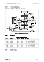
The USIn comprises clock generator, transmitter and receiver. Clock generation logic consists of
synchronization logic for external clock input used by synchronizing or SPI slave operation, and the
baud rate generator for asynchronous or master (synchronous or SPI) operation.

