


Substation A
Substation B
Z
lineAB,1
(pos. seq)
Z
lineAB,0
(zero seq)
Z
lineBC,1
(pos. seq)
Z
lineBC,0
(zero seq)
V
0A
V
0B
3I
0
Phase to ground fault
R
N
Z
T,1
(pos. seq)
Z
T,0
(zero seq)
Source impedance
Z
sc
(pos. seq)
en06000654_ansi.vsd
ANSI06000654 V1 EN
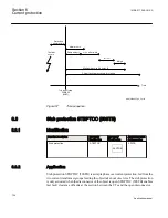
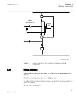
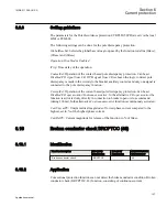
Figure 53:
Equivalent of power system for calculation of setting
The residual fault current can be written:
phase
0
1
0
f
3V
3I
2 Z
Z
3 R
=
×
+
+ ×
EQUATION2023-ANSI V1 EN
(Equation 49)
Where
V
phase
is the phase voltage in the fault point before the fault
Z
1
is the total positive sequence impedance to the fault point. Z
1
= Z
sc
+Z
T,1
+Z
lineAB,1
+Z
lineBC,1
Z
0
is the total zero sequence impedance to the fault point. Z
0
= Z
T,0
+3R
N
+Z
lineAB,0
+Z
lineBC,0
R
f
is the fault resistance.
The residual voltages in stations A and B can be written:
Section 6
1MRK 511 286-UUS A
Current protection
122
Application manual
Содержание REC650 ANSI
Страница 1: ...Relion 650 series Bay control REC650 ANSI Application manual...
Страница 2: ......
Страница 26: ...20...
Страница 66: ...Section 3 1MRK 511 286 UUS A REC650 setting examples 60 Application manual...
Страница 71: ...IED IED ANSI05000460 V2 EN 1MRK 511 286 UUS A Section 4 Analog inputs 65 Application manual...
Страница 82: ...76...
Страница 92: ...86...
Страница 170: ...164...
Страница 176: ...170...
Страница 274: ...268...
Страница 288: ...282...
Страница 350: ...344...
Страница 369: ...363...


