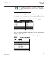
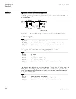


Function description
IEC 61850
identification
IEC 60617
identification
ANSI/IEEE C37.2
device number
Interlocking for 1 1/2 breaker diameter
BH_LINE_B
-
3
Interlocking for double CB bay
DB_BUS_A
-
3
Interlocking for double CB bay
DB_BUS_B
-
3
Interlocking for double CB bay
DB_LINE
-
3
Interlocking for line bay
ABC_LINE
-
3
Interlocking for transformer bay
AB_TRAFO
-
3
10.4.2
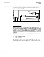
Application
The main purpose of switchgear interlocking is:
•
To avoid the dangerous or damaging operation of switchgear
•
To enforce restrictions on the operation of the substation for other reasons for
example, load configuration. Examples of the latter are to limit the number of parallel
transformers to a maximum of two or to ensure that energizing is always from one
side, for example, the high voltage side of a transformer.
This section only deals with the first point, and only with restrictions caused by switching
devices other than the one to be controlled. This means that switch interlock, because of
device alarms, is not included in this section.
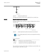
Disconnectors and grounding switches have a limited switching capacity. Disconnectors
may therefore only operate:
•
With basically zero current. The circuit is open on one side and has a small extension.
The capacitive current is small (for example, < 5A) and power transformers with
inrush current are not allowed.
•
To connect or disconnect a parallel circuit carrying load current. The switching
voltage across the open contacts is thus virtually zero, thanks to the parallel circuit
(for example, < 1% of rated voltage). Paralleling of power transformers is not
allowed.
Grounding switches are allowed to connect and disconnect grounding of isolated points.
Due to capacitive or inductive coupling there may be some voltage (for example < 40%
of rated voltage) before grounding and some current (for example < 100A) after
grounding of a line.
Circuit breakers are usually not interlocked. Closing is only interlocked against running
disconnectors in the same bay, and the bus-coupler opening is interlocked during a busbar
transfer.
1MRK 511 286-UUS A
Section 10
Control
225
Application manual
Содержание REC650 ANSI
Страница 1: ...Relion 650 series Bay control REC650 ANSI Application manual...
Страница 2: ......
Страница 26: ...20...
Страница 66: ...Section 3 1MRK 511 286 UUS A REC650 setting examples 60 Application manual...
Страница 71: ...IED IED ANSI05000460 V2 EN 1MRK 511 286 UUS A Section 4 Analog inputs 65 Application manual...
Страница 82: ...76...
Страница 92: ...86...
Страница 170: ...164...
Страница 176: ...170...
Страница 274: ...268...
Страница 288: ...282...
Страница 350: ...344...
Страница 369: ...363...


