


1.
Set
GlobalBaseSel
to
1
,
IBase
= 240 A
2.
Set
DirModeSel1
,
DirModeSel2
and
DirModeSel4
to
Non-directional
3.
Set
DirModeSel3
to
Disabled
3.1.6.2
Calculating settings for step 1
Set the operating residual current level and time delay
1.
Set
Pickup1
to
689%
of
IBase
, corresponding to 1650 A
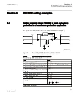
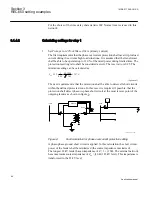
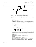
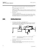
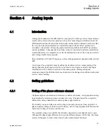
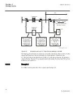
Faults are applied at the 145 kV busbar as shown in figure
.
1
1
1
3
3
Ph-Ph
145 kV
22 kV
ANSI11000126-1-en.vsd
REC650
Y
Y
Y
51N_67N
ANSI11000126 V1 EN
Figure 10:
Fault calculation for 145 kV residual overcurrent protection setting
The following fault types are applied: phase-phase-ground short circuit and phase-
ground-fault. The source impedance (both positive sequence and zero sequence) at
the 145 kV level gives the following residual current from the transformer during a
phase-to-ground busbar fault (the current is hand-calculated but is normally
calculated in a computer).
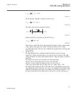
The zero sequence transformer impedance is assumed to be equal to the positive
sequence short circuit impedance:
2
2
0
145
0.12
42
60
N
T
k
N
V
Z
j
e
j
j
S
=
×
=
×
=
W
GUID-50CCC0F7-742D-45C4-84BC-923222214C69-ANSI V1 EN
(Equation 13)
The residual current from the transformer during a single phase-ground-fault and
with maximum short circuit power is:
Section 3
1MRK 511 286-UUS A
REC650 setting examples
52
Application manual
Содержание REC650 ANSI
Страница 1: ...Relion 650 series Bay control REC650 ANSI Application manual...
Страница 2: ......
Страница 26: ...20...
Страница 66: ...Section 3 1MRK 511 286 UUS A REC650 setting examples 60 Application manual...
Страница 71: ...IED IED ANSI05000460 V2 EN 1MRK 511 286 UUS A Section 4 Analog inputs 65 Application manual...
Страница 82: ...76...
Страница 92: ...86...
Страница 170: ...164...
Страница 176: ...170...
Страница 274: ...268...
Страница 288: ...282...
Страница 350: ...344...
Страница 369: ...363...


