


Setting chapter in the application manual explains how the analog input needs to be
set.
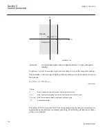
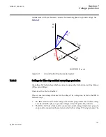
3. The IED is fed from a single voltage transformer connected to the neutral point of a
power transformer in the power system. In this connection the protection is fed by the
voltage VN=V0 (single input). The Setting chapter in the application manual explains
how the analog input needs to be set. ROV2PTOV (59N) will measure the residual
voltage corresponding nominal phase-to-ground voltage for a high impedance
grounded system. The measurement will be based on the neutral voltage
displacement.
Characteristic1:
This parameter gives the type of time delay to be used. The setting can
be,
Definite time
or
Inverse curve A
or
Inverse curve B
or
Inverse curve C
. The choice is
highly dependent of the protection application.
Pickupn
: Set overvoltage operate value for step
n
(
n
=step 1 and 2), given as % of residual
voltage corresponding to global set parameter
VBase
:
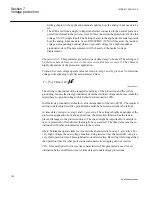
( )
( )
%
3
V
VBase kV
>
×
ANSIEQUATION2290 V1 EN
(Equation 85)
The setting is dependent of the required sensitivity of the protection and the system
grounding. In non-effectively grounded systems the residual voltage can be maximum the
rated phase-to-ground voltage, which should correspond to 100%.
In effectively grounded systems this value is dependent of the ratio Z0/Z1. The required
setting to detect high resistive ground faults must be based on network calculations.
tn
: time delay of step
n
(
n
=step 1 and 2), given in s. The setting is highly dependent of the
protection application. In many applications, the protection function has the task to
prevent damages to the protected object. The speed might be important for example in
case of protection of transformer that might be overexcited. The time delay must be co-
ordinated with other automated actions in the system.
t1Min
: Minimum operate time for inverse time characteristic for step 1, given in s. For
very high voltages the overvoltage function, using inverse time characteristic, can give
very short operation time. This might lead to unselective trip. By setting
t1Min
longer than
the operation time for other protections such unselective tripping can be avoided.
TD1
: Time multiplier for inverse time characteristic. This parameter is used for co-
ordination between different inverse time delayed undervoltage protections.
Section 7
1MRK 511 286-UUS A
Voltage protection
162
Application manual
Содержание REC650 ANSI
Страница 1: ...Relion 650 series Bay control REC650 ANSI Application manual...
Страница 2: ......
Страница 26: ...20...
Страница 66: ...Section 3 1MRK 511 286 UUS A REC650 setting examples 60 Application manual...
Страница 71: ...IED IED ANSI05000460 V2 EN 1MRK 511 286 UUS A Section 4 Analog inputs 65 Application manual...
Страница 82: ...76...
Страница 92: ...86...
Страница 170: ...164...
Страница 176: ...170...
Страница 274: ...268...
Страница 288: ...282...
Страница 350: ...344...
Страница 369: ...363...


