


en04000487_ansi.vsd
Section 1
Section 2
A1A2_DC(BS)
B1B2_DC(BS)
AB_TRAFO
ABC_BC
AB_TRAFO
ABC_BC
(WA1)A1
(WA2)B1
(WA7)C
C
B2
A2
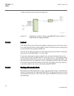
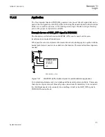
ANSI04000487 V1 EN
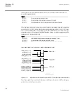
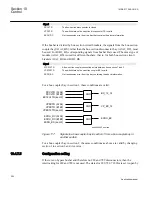
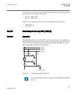
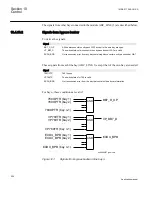
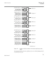
Figure 125:
Busbars divided by bus-section disconnectors (circuit breakers)
The interlocking functionality in 650 series cannot handle the transfer bus
(WA7)C.
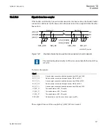
The project-specific logic for input signals concerning bus-coupler are the same as the
specific logic for the line bay (ABC_LINE):
Signal
BC_12_CL
A bus-coupler connection exists between busbar WA1 and WA2.
VP_BC_12
The switch status of BC_12 is valid.
EXDU_BC
No transmission error from bus-coupler bay (BC).
The logic is identical to the double busbar configuration “Signals from bus-coupler“.
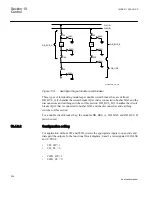
10.4.11.3
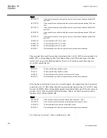
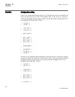
Configuration setting
If there are no second busbar B and therefore no 289 disconnector, then the interlocking
for 289 is not used. The state for 289, 2189G, BC_12 are set to open by setting the
appropriate module inputs as follows. In the functional block diagram, 0 and 1 are
designated 0=FALSE and 1=TRUE:
•
289_OP = 1
•
289QB2_CL = 0
•
2189G_OP = 1
•
2189G_CL = 0
Section 10
1MRK 511 286-UUS A
Control
262
Application manual
Содержание REC650 ANSI
Страница 1: ...Relion 650 series Bay control REC650 ANSI Application manual...
Страница 2: ......
Страница 26: ...20...
Страница 66: ...Section 3 1MRK 511 286 UUS A REC650 setting examples 60 Application manual...
Страница 71: ...IED IED ANSI05000460 V2 EN 1MRK 511 286 UUS A Section 4 Analog inputs 65 Application manual...
Страница 82: ...76...
Страница 92: ...86...
Страница 170: ...164...
Страница 176: ...170...
Страница 274: ...268...
Страница 288: ...282...
Страница 350: ...344...
Страница 369: ...363...


