
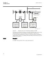


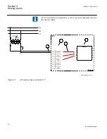


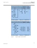


Where:
1)
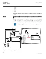
shows how to connect three secondary phase-to-ground voltages to three VT inputs on the IED
2)
is the TRM where these three voltage inputs are located. For these three voltage inputs, the
following setting values shall be entered:
VTprim =66 kV
VTsec = 110 V
Inside the IED, only the ratio of these two parameters is used. It shall be noted that the ratio of
the entered values exactly corresponds to ratio of one individual VT.
66
66
3
110
110
3
=
EQUATION1903 V1 EN
(Equation 22)
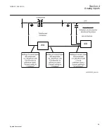
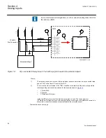
3)
are three connections made in Signal Matrix Tool (SMT), which connect these three voltage
inputs to first three input channels of the preprocessing function block 5). Depending on the
type of functions which need this voltage information, more then one preprocessing block might
be connected in parallel to these three VT inputs.
4)
shows that in this example the fourth (that is, residual) input channel of the preprocessing block
is not connected in SMT tool. Thus the preprocessing block will automatically calculate 3Vo
inside by vectorial sum from the three phase to ground voltages connected to the first three
input channels of the same preprocessing block. .
4)
is a Preprocessing block that has the task to digitally filter the connected analog inputs and
calculate:
•
fundamental frequency phasors for all four input channels
•
harmonic content for all four input channels
•
positive, negative and zero sequence quantities by using the fundamental frequency
phasors for the first three input channels (channel one taken as reference for sequence
quantities)
These calculated values are then available for all built-in protection and control functions within
the IED, which are connected to this preprocessing function block in the configuration tool. For
this application most of the preprocessing settings can be left to the default values. However the
following settings shall be set as shown here:
VBase=66 kV (that is, rated Ph-Ph voltage)
If frequency tracking and compensation is required (this feature is typically required only for
IEDs installed in the generating stations) then the setting parameters
DFTReference shall be
set accordingly.
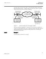
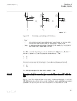
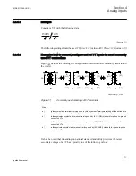
4.2.4.4
Example on how to connect a phase-to-phase connected VT to the IED
gives an example how to connect a phase-to-phase connected VT to the IED. It
gives an overview of the required actions by the user in order to make this measurement
available to the built-in protection and control functions within the IED as well. It shall be
noted that this VT connection is only used on lower voltage levels (that is, rated primary
voltage below 40 kV).
1MRK 511 286-UUS A
Section 4
Analog inputs
73
Application manual
Содержание REC650 ANSI
Страница 1: ...Relion 650 series Bay control REC650 ANSI Application manual...
Страница 2: ......
Страница 26: ...20...
Страница 66: ...Section 3 1MRK 511 286 UUS A REC650 setting examples 60 Application manual...
Страница 71: ...IED IED ANSI05000460 V2 EN 1MRK 511 286 UUS A Section 4 Analog inputs 65 Application manual...
Страница 82: ...76...
Страница 92: ...86...
Страница 170: ...164...
Страница 176: ...170...
Страница 274: ...268...
Страница 288: ...282...
Страница 350: ...344...
Страница 369: ...363...


