


The positions of all switching devices in a bay and from some other bays determine the
conditions for operational interlocking. Conditions from other stations are usually not
available. Therefore, a line grounding switch is usually not fully interlocked. The operator
must be convinced that the line is not energized from the other side before closing the
grounding switch. As an option, a voltage indication can be used for interlocking. Take
care to avoid a dangerous
enable
condition at the loss of a VT secondary voltage, for
example, because of a blown fuse.
The switch positions used by the operational interlocking logic are obtained from
auxiliary contacts or position sensors. For each end position (open or closed) a true
indication is needed - thus forming a double indication. The apparatus control function
continuously checks its consistency. If neither condition is high (1 or TRUE), the switch
may be in an intermediate position, for example, moving. This dynamic state may
continue for some time, which in the case of disconnectors may be up to 10 seconds.
Should both indications stay low for a longer period, the position indication will be
interpreted as
unknown
. If both indications stay high, something is wrong, and the state is
again treated as
unknown
.
In both cases an alarm is sent to the operator. Indications from position sensors shall be
self-checked and system faults indicated by a fault signal. In the interlocking logic, the
signals are used to avoid dangerous
enable
or
release
conditions. When the switching state
of a switching device cannot be determined operation is not permitted.
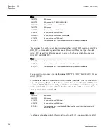
10.4.3
Configuration guidelines
The following sections describe how the interlocking for a certain switchgear
configuration can be realized in the IED by using standard interlocking modules and their
interconnections. They also describe the configuration settings. The inputs for delivery
specific conditions (Qx_EXy) are set to 1=TRUE if they are not used, except in the
following cases:
•
989_EX2 and 989_EX4 in modules BH_LINE_A and BH_LINE_B
•
152_EX3 in module AB_TRAFO
when they are set to 0=FALSE.
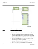
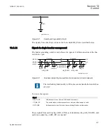
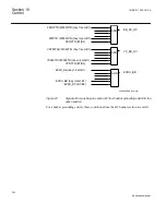
10.4.4
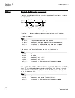
Interlocking for busbar grounding switch BB_ES (3)
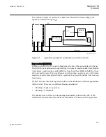
10.4.4.1
Application
The interlocking for busbar grounding switch (BB_ES, 3) function is used for one busbar
grounding switch on any busbar parts according to figure
.
Section 10
1MRK 511 286-UUS A
Control
226
Application manual
Содержание REC650 ANSI
Страница 1: ...Relion 650 series Bay control REC650 ANSI Application manual...
Страница 2: ......
Страница 26: ...20...
Страница 66: ...Section 3 1MRK 511 286 UUS A REC650 setting examples 60 Application manual...
Страница 71: ...IED IED ANSI05000460 V2 EN 1MRK 511 286 UUS A Section 4 Analog inputs 65 Application manual...
Страница 82: ...76...
Страница 92: ...86...
Страница 170: ...164...
Страница 176: ...170...
Страница 274: ...268...
Страница 288: ...282...
Страница 350: ...344...
Страница 369: ...363...


