


temperature, ambient air temperature, way of laying of cable and ground thermal
resistivity. From manuals for overhead conductor temperatures and corresponding current
is given.
Tau
: The thermal time constant of the protected circuit given in minutes. Please refer to
manufacturers manuals for details.
TripTemp
: Temperature value for trip of the protected circuit. For cables, a maximum
allowed conductor temperature is often stated to be 190°F (88°C). For overhead lines, the
critical temperature for aluminium conductor is about 190-210°F (88-99°C). For a copper
conductor a normal figure is 160°F (71°C).
AlarmTemp
: Temperature level for alarm of the protected circuit. ALARM signal can be
used as a warning before the circuit is tripped. Therefore the setting shall be lower than the
trip level. It shall at the same time be higher than the maximum conductor temperature at
normal operation. For cables this level is often given to 150°F (66°C). Similar values are
stated for overhead lines. A suitable setting can be about 60°F (16°C) below the trip value.
ReclTemp
: Temperature where lockout signal LOCKOUT from the protection is released.
When the thermal overload protection trips a lock-out signal is activated. This signal is
intended to block switch in of the protected circuit as long as the conductor temperature
is high. The signal is released when the estimated temperature is below the set value. This
temperature value should be chosen below the alarm temperature.
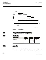
6.7
Breaker failure protection 3-phase activation and output
CCRBRF (50BF)
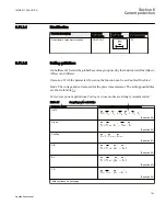
6.7.1
Identification
Function description
IEC 61850
identification
IEC 60617
identification
ANSI/IEEE C37.2
device number
Breaker failure protection, 3-phase
activation and output
CCRBRF
3I>BF
SYMBOL-U V1 EN
50BF
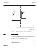
6.7.2
Application
In the design of the fault clearance system the N-1 criterion is often used. This means that
a fault needs to be cleared even if any component in the fault clearance system is faulty.
Section 6
1MRK 511 286-UUS A
Current protection
130
Application manual
Содержание REC650 ANSI
Страница 1: ...Relion 650 series Bay control REC650 ANSI Application manual...
Страница 2: ......
Страница 26: ...20...
Страница 66: ...Section 3 1MRK 511 286 UUS A REC650 setting examples 60 Application manual...
Страница 71: ...IED IED ANSI05000460 V2 EN 1MRK 511 286 UUS A Section 4 Analog inputs 65 Application manual...
Страница 82: ...76...
Страница 92: ...86...
Страница 170: ...164...
Страница 176: ...170...
Страница 274: ...268...
Страница 288: ...282...
Страница 350: ...344...
Страница 369: ...363...


