


ANSI12000025-1-en.vsd
ANSI12000025 V1 EN
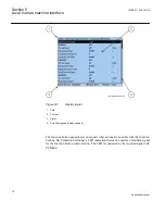
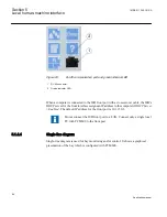
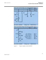
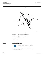
Figure 26:
Function button panel
The alarm LED panel shows on request the alarm text labels for the alarm LEDs. Three
alarm LED pages are available.
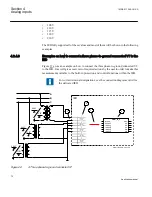
GUID-D20BB1F1-FDF7-49AD-9980-F91A38B2107D V1 EN
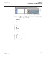
Figure 27:
Alarm LED panel
The function button and alarm LED panels are not visible at the same time. Each panel is
shown by pressing one of the function buttons or the Multipage button. Pressing the ESC
button clears the panel from the display. Both the panels have dynamic width that depends
on the label string length that the panel contains.
5.1.2
LEDs
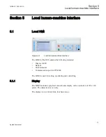
The LHMI includes three protection status LEDs above the display: Normal, Pickup and
Trip.
There are 15 programmable alarm LEDs on the front of the LHMI. Each LED can indicate
three states with the colors: green, yellow and red. The alarm texts related to each three-
color LED are divided into three pages.
1MRK 511 286-UUS A
Section 5
Local human-machine interface
79
Application manual
Содержание REC650 ANSI
Страница 1: ...Relion 650 series Bay control REC650 ANSI Application manual...
Страница 2: ......
Страница 26: ...20...
Страница 66: ...Section 3 1MRK 511 286 UUS A REC650 setting examples 60 Application manual...
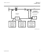
Страница 71: ...IED IED ANSI05000460 V2 EN 1MRK 511 286 UUS A Section 4 Analog inputs 65 Application manual...
Страница 82: ...76...
Страница 92: ...86...
Страница 170: ...164...
Страница 176: ...170...
Страница 274: ...268...
Страница 288: ...282...
Страница 350: ...344...
Страница 369: ...363...


