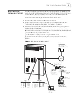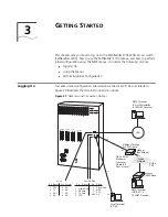
Step 4: Connect I/O Cabling and Wiring
49
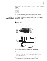
Figure 24
PathBuilder S700 Alarm Connectors
Connecting the External Alarm
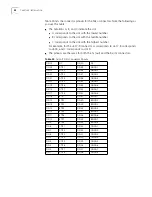
Table 19 lists the pinouts for the external
alarm connector. You can connect up to three alarms from outside equipment
using the specified pairs of pins (pins 5 and 9 for alarm #1, pins 8 and 3 for alarm
#2, and pins 2 and 6 for alarm #3). Set the state of these alarms to
Normally Open
or
Normally Closed
from the Shelf Configuration menu. See “Setting External
Alarm Status” in Chapter 5 for details.
Table 19
External Alarm Connector Pinouts
PIN 5
External Alarm #1
PIN 9
External Alarm #1 Return
PIN 8
External Alarm #2
PIN 3
External Alarm #2 Return
PIN 2
External Alarm #3
PIN 6
External Alarm #3 Return
PINS 1, 4, 7
No Connect
TX RX
TX RX
TX RX
TX RX
Visual Alarm
Audible Alarm
External Alarm
Содержание 3C63400-3AC-C - PathBuilder S700 Switch
Страница 14: ...xiv CHAPTER SUPPLEMENTARY REGULATORY INFORMATION ...
Страница 18: ...4 ABOUT THIS GUIDE ...
Страница 28: ...14 CHAPTER 1 SYSTEM DESCRIPTION ...
Страница 88: ...74 CHAPTER 3 GETTING STARTED ...
Страница 260: ...246 CHAPTER 6 PATHBUILDER S700 DIAGNOSTICS AND PERFORMANCE MONITORING ...
Страница 270: ...256 INDEX ...


