30
C
HAPTER
2: I
NSTALLATION
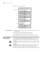
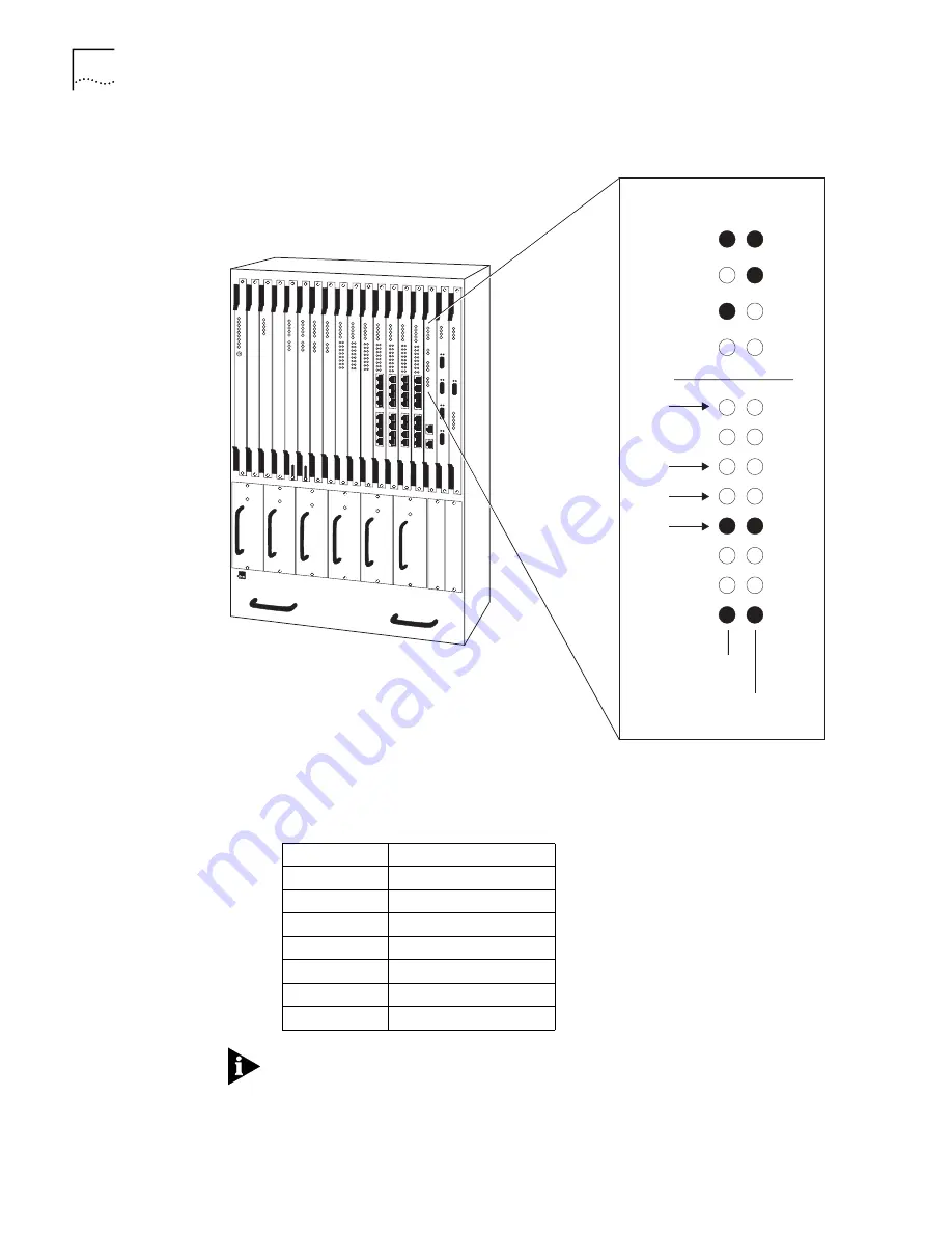
Figure 14
Ethernet Module LEDs
Connecting a DSX-1 CBR
or E1 CBR Module
Connect a DSX-1 CBR or E1 CBR module using the RJ48 DSX-1 interface for T1/E1
traffic. Table 9 describes the DSX-1/E1 CBR connector pinouts.
The PathBuilder S700 supports two models of DSX-1/E1 CBR modules:
front-connecting modules, which you connect from the front of the unit, as
described in this section, and rear redundant modules, which you connect from
the rear of the unit. For details about how to connect rear redundant DSX-1/E1
CBR modules, see “Connecting Rear Redundant Modules” later in this chapter.
PathBuilder S700
Power
Up
1.
2.
Power
Inservice
Fail
Test
Fwd
ATM
Tx
Rx
Link
Tx
Rx
Link
Power On
Test Complete
Bridge
Data If
Blinking
Blinks
With
Data
Should
Be On
When
Properly
Connected
To 10BASE-T
Common System
Table 9
DSX-1/E1 CBR Connector Pinouts
PIN 1
RX ring
PIN 2
RX tip
PIN 3
NC
PIN 4
TX ring
PIN 5
TX tip
PIN 6
NC
PIN 7
NC
PIN 8
NC
Содержание 3C63400-3AC-C - PathBuilder S700 Switch
Страница 14: ...xiv CHAPTER SUPPLEMENTARY REGULATORY INFORMATION ...
Страница 18: ...4 ABOUT THIS GUIDE ...
Страница 28: ...14 CHAPTER 1 SYSTEM DESCRIPTION ...
Страница 88: ...74 CHAPTER 3 GETTING STARTED ...
Страница 260: ...246 CHAPTER 6 PATHBUILDER S700 DIAGNOSTICS AND PERFORMANCE MONITORING ...
Страница 270: ...256 INDEX ...

