Step 4: Connect I/O Cabling and Wiring
27
Connecting a DS1/E1
UNI with IMA Module
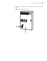
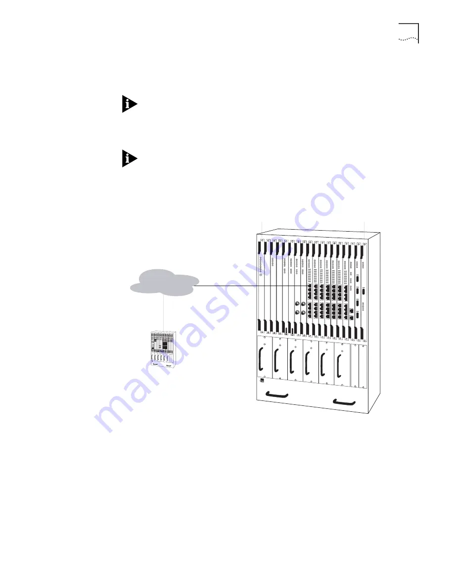
Connect the DS1 UNI with IMA module or the E1 UNI with IMA module using the
RJ-48 connectors (with integrated CSU for the DS1 module, with no CSU for the
E1 module), as shown in Figure 11.
The PathBuilder S700 supports two models of DS1/E1 UNI modules:
front-connecting modules, which you connect from the front of the unit, as
described in this section, and rear redundant modules, which you connect from
the rear of the unit. For details about how to connect rear redundant DS1/E1 UNI
modules, see “Connecting Rear Redundant Modules” later in this chapter.
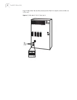
If you are using a G703 coax physical connection to connect the E1 line to the
interface, you must use the E1 Balun Adapter (part number 3C63904) for proper
impedance.
Figure 11
DS1/E1 UNI with IMA Module Connection
Once you have connected the module, verify the front-panel indicators. As shown
in Figure 12, the DS1/E1 UNI with IMA module features eight pairs of port
indicator LEDs in addition to the common system front panel indicators—each pair
corresponds to one of the eight RJ48 interfaces on the DS1/E1 UNI module.
DS1/E1
n
x T1 or E1
PathBuilder S700
PathBuilder S700
PathBuilder S700
ATM
Slot 1
Slot 18
Содержание 3C63400-3AC-C - PathBuilder S700 Switch
Страница 14: ...xiv CHAPTER SUPPLEMENTARY REGULATORY INFORMATION ...
Страница 18: ...4 ABOUT THIS GUIDE ...
Страница 28: ...14 CHAPTER 1 SYSTEM DESCRIPTION ...
Страница 88: ...74 CHAPTER 3 GETTING STARTED ...
Страница 260: ...246 CHAPTER 6 PATHBUILDER S700 DIAGNOSTICS AND PERFORMANCE MONITORING ...
Страница 270: ...256 INDEX ...

