22
C
HAPTER
2: I
NSTALLATION
Step 4: Connect I/O
Cabling and Wiring
This section tells you how to connect I/O cabling and wiring once the modules are
installed in the shelf and describes the common and module-specific front panel
LEDs.
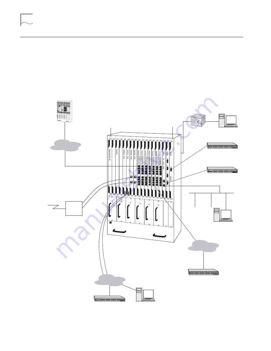
Figure 6 shows an example of a PathBuilder S700 configuration with all of the
associated cabling connected.
Figure 6
Sample Full System Configuration
PathBuilder S700
RX
In
TX Out
75 ohm coax
DS3/E3
CSU or CPE
DS3/E3
Service
TX Out
TX In
Slot 1
Slot 18
VT100 T
Initial Management
Connection to
Add an IP
Address for LAN
Management
Network
Management
Station
OC3 UNI Multi-Mode
OC3 UNI Single-Mode
ATM
DS1/E1
n
x T1 or E1
PathBuilder S700
PathBuilder S700
ATM
n
x 64K
LAN
Router
V.35
EIA530
RS-422
HSSI
Frame Relay
Router
Router
Router
Содержание 3C63400-3AC-C - PathBuilder S700 Switch
Страница 14: ...xiv CHAPTER SUPPLEMENTARY REGULATORY INFORMATION ...
Страница 18: ...4 ABOUT THIS GUIDE ...
Страница 28: ...14 CHAPTER 1 SYSTEM DESCRIPTION ...
Страница 88: ...74 CHAPTER 3 GETTING STARTED ...
Страница 260: ...246 CHAPTER 6 PATHBUILDER S700 DIAGNOSTICS AND PERFORMANCE MONITORING ...
Страница 270: ...256 INDEX ...


