186
C
HAPTER
5: C
ONFIGURING
P
ATH
B
UILDER
S700 M
ODULES
, P
ORTS
,
AND
A
PPLICATIONS
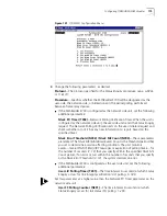
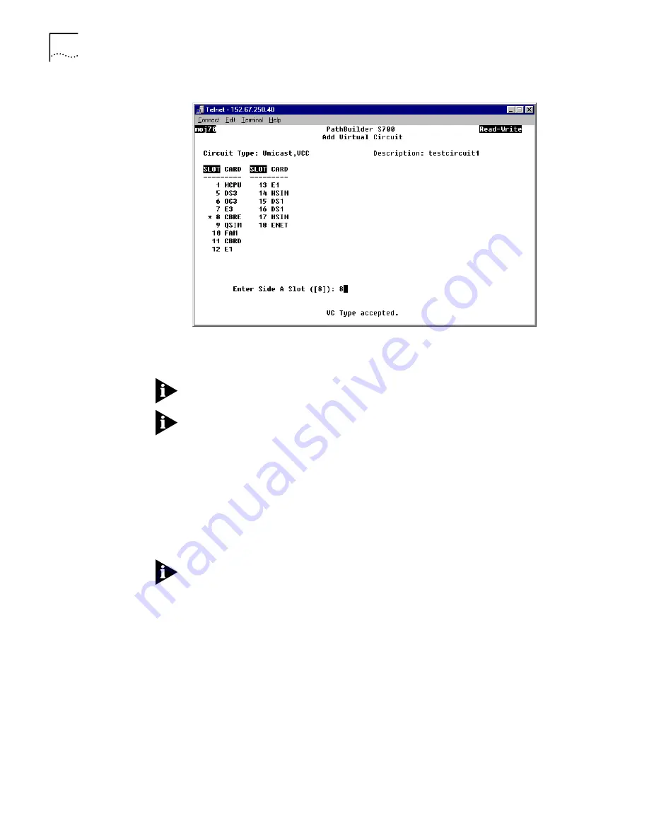
Figure 148
Add Virtual Circuit Screen—Specifying the Slot # for Side A
3
Enter the slot number for the card that you want to define as side A of the virtual
circuit. For example, from the Add Virtual Circuit screen show in Figure 148, if you
wanted to select the E3 UNI card as side A, you would enter
7
.
The default slot number is indicated by an asterisk. To select the default slot
number, simply press [Enter].
You can also create an in-band circuit between two nodes by defining the
PathBuilder S700 MCPU slot—with its own IP address—as one side of the virtual
circuit. This enables you to manage a remote hub from a local network
management station. See “Configuring In-band Management” in Chapter 3 for
details.
After you enter the slot number, the Add Virtual Circuit screen displays the
selected slot number and card type, lists the parameters you will enter for side A of
the circuit, and prompts you to set the first parameter, as shown in Figure 149. For
parameter descriptions, by card, see “Virtual Circuit Parameters” later in this
chapter.
If the card you select has multiple ports, you are prompted to specify the port
number as the first parameter for side A of the circuit.
Содержание 3C63400-3AC-C - PathBuilder S700 Switch
Страница 14: ...xiv CHAPTER SUPPLEMENTARY REGULATORY INFORMATION ...
Страница 18: ...4 ABOUT THIS GUIDE ...
Страница 28: ...14 CHAPTER 1 SYSTEM DESCRIPTION ...
Страница 88: ...74 CHAPTER 3 GETTING STARTED ...
Страница 260: ...246 CHAPTER 6 PATHBUILDER S700 DIAGNOSTICS AND PERFORMANCE MONITORING ...
Страница 270: ...256 INDEX ...

