Step 4: Connect I/O Cabling and Wiring
53
To enable the BITS clock, you must make the following jumper settings on the STX
module:
JP9 (1-5)
JP9 (2-6)
JP9 (3-9)
JP9 (4-10)
For information about how to select the BITS clock as the source for system
timing, see “Managing the System Clock” in Chapter 5.
Connecting Rear
Redundant Modules
The following PathBuilder S700 modules are available in either front-connecting or
rear redundant models:
n
DS3/E3 UNI
n
DS1/E1 UNI with Inverse Multiplexing for ATM (IMA)
n
DSX-1/E1 CBR
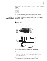
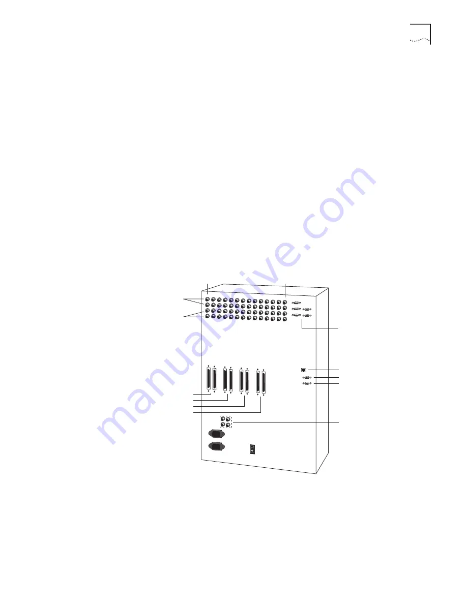
Figure 27 illustrates the locations of the connectors on the rear of the unit.
Figure 27
PathBuilder S700 Rear Connectors
When connecting rear redundant modules, follow these guidelines:
n
Connect DS3 UNI or E3 UNI modules to DS3 or E3 repeaters using the pair of
BNC connectors corresponding to the slot(s) in which you have the DS3/E3 UNI
module(s) installed. For example, if you had a DS3 UNI module installed in slot
7, you would use the connectors in the third column from the right. For this
release, use only the bottom two rows of connectors; the top two rows are
reserved for future expansion.
n
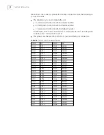
Connect DS1/E1 UNI or DSX-1/E1 CBR modules to the pair of Telco connectors
corresponding to the slot(s) in which the module(s) are installed.
Slot 18
Slot 5
Port 2
DS3/E3
Port 1
DS3/E3
TX RX
TX RX
TX RX
TX RX
Slots 1-4
10BaseT
RS-232
SLIP
Slots 16-18
Slots 13-15
Slots 10-12
Slots 7-9
TX
RX
TX
RX
Reserved
for later use
Содержание 3C63400-3AC-C - PathBuilder S700 Switch
Страница 14: ...xiv CHAPTER SUPPLEMENTARY REGULATORY INFORMATION ...
Страница 18: ...4 ABOUT THIS GUIDE ...
Страница 28: ...14 CHAPTER 1 SYSTEM DESCRIPTION ...
Страница 88: ...74 CHAPTER 3 GETTING STARTED ...
Страница 260: ...246 CHAPTER 6 PATHBUILDER S700 DIAGNOSTICS AND PERFORMANCE MONITORING ...
Страница 270: ...256 INDEX ...


