28
C
HAPTER
2: I
NSTALLATION
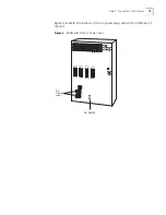
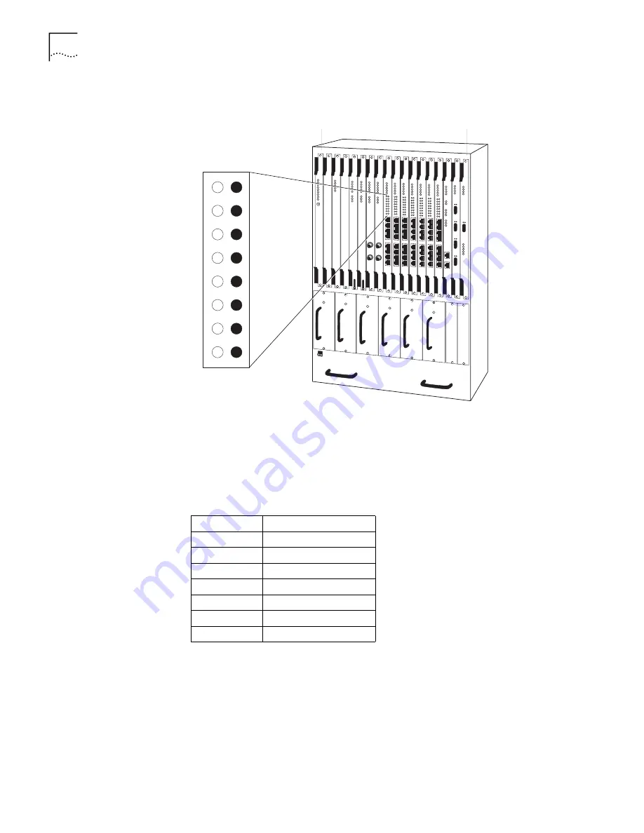
Figure 12
DS1/E1 UNI LEDs
n
The green indicator light illuminates to show that the port is in service.
n
The red indicator light illuminates to show that the port is not in service.
Connecting an Ethernet
Module
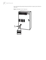
Connect an Ethernet module to the LAN directly or through a hub, as shown in
Figure 13, Table 8 lists the RJ48 connector pinouts.
The cable runs from the PathBuilder S700 Ethernet ports to the Ethernet LAN
connections must be no longer than 100 meters in compliance with EIA/TIA
standards for 10BaseT. The cable lengths should include service loops at the ends
and the complete cable route distances.
PathBuilder S700
Slot 1
Slot 18
Table 8
Ethernet Module Connector Pinouts
PIN 1
TX+
PIN 2
TX-
PIN 3
RX+
PIN 4
PIN 5
PIN 6
RX-
PIN 7
PIN 8
Содержание 3C63400-3AC-C - PathBuilder S700 Switch
Страница 14: ...xiv CHAPTER SUPPLEMENTARY REGULATORY INFORMATION ...
Страница 18: ...4 ABOUT THIS GUIDE ...
Страница 28: ...14 CHAPTER 1 SYSTEM DESCRIPTION ...
Страница 88: ...74 CHAPTER 3 GETTING STARTED ...
Страница 260: ...246 CHAPTER 6 PATHBUILDER S700 DIAGNOSTICS AND PERFORMANCE MONITORING ...
Страница 270: ...256 INDEX ...


