16
C
HAPTER
2: I
NSTALLATION
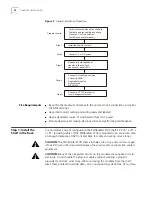
Figure 2
General Installation Procedure
Site Requirements
n
Be within the maximum distances to the port and trunk connections, as well as
the NMS terminal
n
Have interconnect cabling and wiring ready and labeled
n
Have a dedicated source of switched and fused AC power.
n
Provide clearance for making all connections and performing maintenance.
Step 1: Install the
Shelf in the Rack
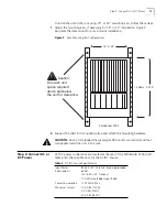
In a normal rack mount configuration the PathBuilder S700 shelf is 22.75" x 19" x
11.81" including cables. If the PathBuilder S700 is mounted in an enclosure, plan
on enough clearance at the front and back for cable and wiring service loops.
CAUTION:
The PathBuilder S700 chassis includes a fan tray, and a minimum gap
of one RU (rack unit) is required between the chassis and any convection cooled
equipment.
CAUTION:
Many of the integrated circuits on the modules are sensitive to static
electricity. Do not handle the plug-in modules without wearing a properly
grounded, antistatic, wrist strap. When removing the modules from the shelf,
place them printed-circuit side down on a nonconducting, static-free, flat surface.
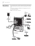
Verify clearances around the shelf site
Fabricate and run cabling and wiring
Prepare AC or DC power run
(install fuse and alarm panel)
Install the shelf in the rack
Step 1
Connect AC or DC power
Step 2
Connect I/O cabling and wiring
and verify LEDs:
Application modules
Office alarms
BITS clock
Step 4
Connect a VT100 terminal for
local management access
Step 5
Step 3
(If needed) Install additional
modules in the shelf and
monitor front-panel LEDs
Prepare the site:
Содержание 3C63400-3AC-C - PathBuilder S700 Switch
Страница 14: ...xiv CHAPTER SUPPLEMENTARY REGULATORY INFORMATION ...
Страница 18: ...4 ABOUT THIS GUIDE ...
Страница 28: ...14 CHAPTER 1 SYSTEM DESCRIPTION ...
Страница 88: ...74 CHAPTER 3 GETTING STARTED ...
Страница 260: ...246 CHAPTER 6 PATHBUILDER S700 DIAGNOSTICS AND PERFORMANCE MONITORING ...
Страница 270: ...256 INDEX ...


