


6-32
IM DL850-03EN
Item
Specifications
Precautions
• Highly sensitive measurements are made in the µV level in strain measurements. Therefore,
take measures against noise at the strain sensor perimeter, bridge head, and cable wiring.
• Depending on the noise environment, an error may result in the balance. Check the
influence before making measurements.
• The bridge head specified by YOKOGAWA has high noise resistance.
• Some of the strain gauge sensors and bridge heads made by other manufacturers
do not have sensing wires connected. (No such problems with bridge heads made by
YOKOGAWA.) If such products are used, an error may result in the bridge voltage leading
to measurement errors, because sensing does not work effectively. If possible, it is desirable
that sensing be done very close to the bridge. However, if this is not possible, use the NDIS
conversion cable (DV450-001) that is sold separately by YOKOGAWA.
Outline specifications of the DV450-001: Sensing cable, NDIS male-female, 30 cm in length,
insert it as close to the bridge as possible
• The connector shell is connected to the case potential.
• When a bridge head (701955 or 701956) is used, the connector shell, cable shield, and the
bridge head case are all connected to the case potential of the DL850/DL850V.
• When a bridge head (701955 or 701956) is used, the floating GND is connected to the
bridge head case inside the bridge head.
• Be sure to execute balancing again when you change the range or the bridge voltage.
1 Value measured under standard operating conditions.
2 The typical value is a representative or standard value. It is not strictly warranted.
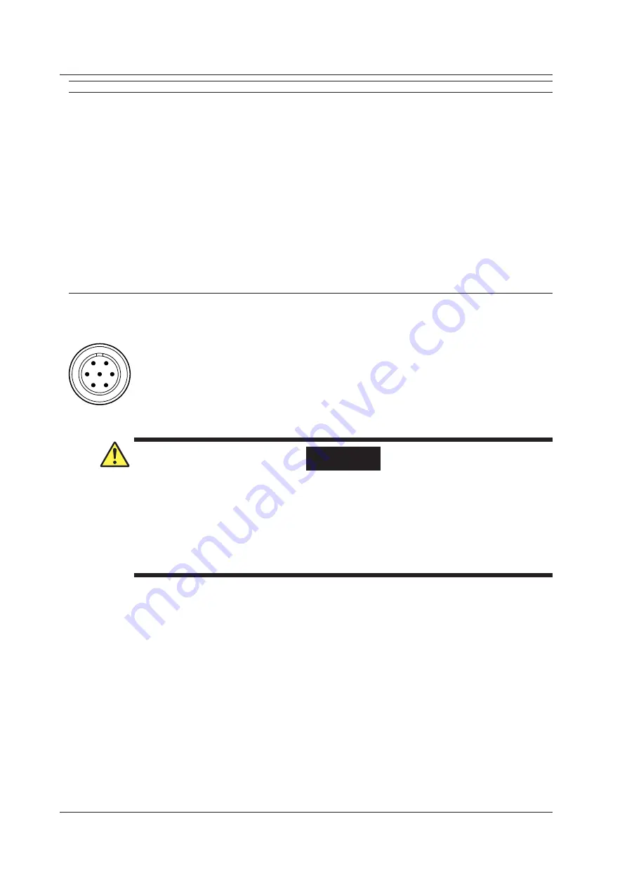
Module front View
The connector shell is connected to the case potential.
A: (positive bridge voltage)
B: Input- (negative measurement signal)
C: Bridge- (negative bridge voltage)
D: Input+ (positive measurement signal)
E: Floating common
F: Sense+ (positive bridge voltage sensing)
G: Sense- (positive bridge voltage sensing)
F
E
D
C
B
A
G
WARNING
• Do not apply input voltage exceeding the maximum input voltage or allowable common
mode input voltage.
• To prevent the possibility of electric shock, be sure to furnish protective earth grounding of
the DL850/DL850V.
• To prevent the possibility of electric shock, be sure to fasten the module screws.
Otherwise, the electrical and mechanical protection functions will not be activated.
• Avoid continuous connection under an environment in which the surge voltage may occur.
6.13 Module Specifications