5-10
WATER PUMP
COOL
a
b
NOTE:
NOTE:
10 Nm (1.0 m
kg)
10 Nm (1.0 m
kg)
NOTE:
Align the slot
a
on the impeller shaft with
the projection
b
on the oil pump shaft.
Before installing the water pump housing,
apply a thin coat of lithium soap base
grease onto the O-ring.
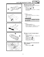
2. Install:
water pump housing cover
1
water pump outlet pipe
2
Always use a new gasket and O-rings.
Before installing the water pump outlet pipe,
apply a thin coat of lithium soap base grease
onto the O-rings.
Water pump housing cover bolt
10 Nm (1.0 m
kg)
3. Install:
gasket
dowel pins
drive chain sprocket cover
1
4. Install:
shift arm
1
Align the slot
a
on the shift arm
1
with the
punch mark
b
on the shift shaft
2
.
5. Fill:
cooling system
(with the specified amount of the recom-
mended coolant)
Refer to “CHANGING THE COOLANT” in
chapter 3.
6. Check:
cooling system
Leaks
Repair or replace any faulty part.
7. Measure:
radiator cap opening pressure
Below the specified pressure
Replace
the radiator cap.
Refer to “CHECKING THE RADIATOR”.
Summary of Contents for 1998 FZS600 5DM1-AE1
Page 1: ......
Page 2: ......
Page 8: ......
Page 9: ...GEN INFO 1 ...
Page 11: ...GEN INFO ...
Page 20: ...SPEC 2 ...
Page 22: ...SPEC ...
Page 46: ...2 24 1 2 LUBRICATION DIAGRAMS SPEC 1 Camshaft 2 Crankshaft ...
Page 54: ...SPEC ...
Page 55: ...CHK ADJ 3 ...
Page 57: ...CHK ADJ ...
Page 109: ...CHK ADJ ...
Page 110: ...ENG 4 ...
Page 189: ...COOL 5 ...
Page 191: ...COOL ...
Page 202: ...CARB 6 ...
Page 204: ...CARB ...
Page 216: ...6 12 CARB ...
Page 217: ...CHAS 7 ...
Page 288: ...ELEC 8 ...
Page 290: ...ELEC ...
Page 292: ...8 2 CIRCUIT DIAGRAM ELEC CIRCUIT DIAGRAM ...
Page 326: ...8 36 SIGNAL SYSTEM ELEC EB806000 SIGNAL SYSTEM CIRCUIT DIAGRAM ...
Page 355: ...TRBL SHTG 9 ...
Page 357: ...TRBL SHTG ...
Page 363: ...TRBL SHTG ...


