4-13
CAMSHAFT
ENG
c
c
d
d
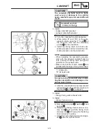
CAUTION:
Always use a new gasket.
Timing chain tensioner bolt
10 Nm (1.0 m
kg)
d. Install the springs
3
, washer
2
, and cap
bolt
1
.
Cap bolt
20 Nm (2.0 m
kg)
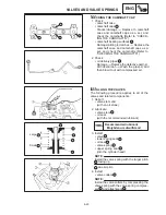
7. Turn:
crankshaft
(several full turns counterclockwise)
8. Check:
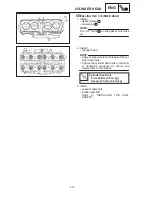
“T” mark
a
Make sure that the “T” mark on the magne-
to rotor is aligned with the stationary point-
er
b
on the crankcase.
camshaft punch marks
c
Make sure that the punch marks on the
camshafts are aligned with the embossed
marks
d
on the camshaft cap.
Out of alignment
Adjust.
Refer to the installation steps above.
9. Tighten:
camshaft sprocket bolts
Be sure to tighten the camshaft sprocket
bolts to the specified torque to avoid the
possiblity of the bolts coming loose and
damaging the engine.
Camshaft sprocket bolt
24 Nm (2.4 m
kg)
10. Measure:
valve clearance
Out of specification
Adjust.
Refer to “ADJUSTING THE VALVE
CLEARANCE” in chapter 3.
Summary of Contents for 1998 FZS600 5DM1-AE1
Page 1: ......
Page 2: ......
Page 8: ......
Page 9: ...GEN INFO 1 ...
Page 11: ...GEN INFO ...
Page 20: ...SPEC 2 ...
Page 22: ...SPEC ...
Page 46: ...2 24 1 2 LUBRICATION DIAGRAMS SPEC 1 Camshaft 2 Crankshaft ...
Page 54: ...SPEC ...
Page 55: ...CHK ADJ 3 ...
Page 57: ...CHK ADJ ...
Page 109: ...CHK ADJ ...
Page 110: ...ENG 4 ...
Page 189: ...COOL 5 ...
Page 191: ...COOL ...
Page 202: ...CARB 6 ...
Page 204: ...CARB ...
Page 216: ...6 12 CARB ...
Page 217: ...CHAS 7 ...
Page 288: ...ELEC 8 ...
Page 290: ...ELEC ...
Page 292: ...8 2 CIRCUIT DIAGRAM ELEC CIRCUIT DIAGRAM ...
Page 326: ...8 36 SIGNAL SYSTEM ELEC EB806000 SIGNAL SYSTEM CIRCUIT DIAGRAM ...
Page 355: ...TRBL SHTG 9 ...
Page 357: ...TRBL SHTG ...
Page 363: ...TRBL SHTG ...


