8-3
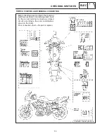
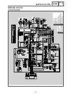
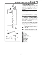
1 A.C. magneto
2 Rectifier regulator
3 Main switch
4 Battery
5 Fuse (back up)
6 Fuse (main)
7 Starter relay
8 Starter motor
9 Starting circuit cut-off relay
10
Fuel pump relay
11
Ignitor unit
12
Ignition coil
13
Spark plug
14
Pickup coil
15
Throttle position sensor
16
Neutral switch
17
Speed sensor
18
Fuel sender
19
Thermo switch (warning light)
20
Diode
21
Fuel pump
22
Sidestand switch
23
Speedometer
24
Tachometer
25
Fuel meter
26
Fuel level warning light
27
Engine temperature warning light
28
Neutral indicator light
29
Oil level warning light
CIRCUIT DIAGRAM
ELEC
30
High beam indicator light
31
Turn indicator lights
32
Meter lights
33
Clutch switch
34
Oil level switch
35
Flasher relay
36
Horn
37
Pass switch
38
Dimmer switch
39
Horn switch
40
Turn switch
41
Front turn signal lights
42
Rear turn signal lights
43
Head light
44
Tail / Brake light
45
Auxiliary light
46
Fan motor
47
Thermo switch (fan motor)
48
Fuse (fan)
49
Fuse (head)
50
Rear brake switch
51
Fuse (signal)
52
Front brake switch
53
Lights switch
54
Engine stop switch
55
Starter switch
56
Fuse (ignition)
57
Alarm (option)
NOTE:
B
Black
Br
Brown
Ch
Chocolate
Dg
Dark green
G
Green
L
Blue
Lg
Light green
O
Orange
Sb
Sky blue
P
Pink
R
Red
Y
Yellow
W
White
B/ L
Black/ Blue
B/ R Black/ Red
B/ Y
Black/ Yellow
Br / L Brown / Blue
Br / W Brown / White
G / R Green / Red
G / W Green / White
G / Y Green / Yellow
L / B
Blue/ Black
L / Y
Blue/ Yellow
L / W Blue/ White
L / R
Blue/ Red
R/ B Red / Black
R/ Y Red / Yellow
R/ W Red / White
Y/ B
Yellow / Black
Y/ R Yellow / White
W/ B White / Black
W/ G White / Green
Starter switch is closed while the button (switch) is pushed.
Sidestand switch is closed while the side stand is upped.
Clutch switch is closed while the clutch lever is pulled.
Brake switch is closed while the brake is applied.
COLOR CODE
Summary of Contents for 1998 FZS600 5DM1-AE1
Page 1: ......
Page 2: ......
Page 8: ......
Page 9: ...GEN INFO 1 ...
Page 11: ...GEN INFO ...
Page 20: ...SPEC 2 ...
Page 22: ...SPEC ...
Page 46: ...2 24 1 2 LUBRICATION DIAGRAMS SPEC 1 Camshaft 2 Crankshaft ...
Page 54: ...SPEC ...
Page 55: ...CHK ADJ 3 ...
Page 57: ...CHK ADJ ...
Page 109: ...CHK ADJ ...
Page 110: ...ENG 4 ...
Page 189: ...COOL 5 ...
Page 191: ...COOL ...
Page 202: ...CARB 6 ...
Page 204: ...CARB ...
Page 216: ...6 12 CARB ...
Page 217: ...CHAS 7 ...
Page 288: ...ELEC 8 ...
Page 290: ...ELEC ...
Page 292: ...8 2 CIRCUIT DIAGRAM ELEC CIRCUIT DIAGRAM ...
Page 326: ...8 36 SIGNAL SYSTEM ELEC EB806000 SIGNAL SYSTEM CIRCUIT DIAGRAM ...
Page 355: ...TRBL SHTG 9 ...
Page 357: ...TRBL SHTG ...
Page 363: ...TRBL SHTG ...


