2-13
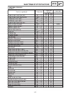
MAINTENANCE SPECIFICATIONS
SPEC
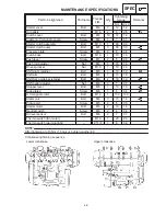
NOTE:
Part to be tightened
Thread size
Tightening
torque
Remarks
g
Nm
m
kg
Side cover and frame
M6
1.0
4
0.4
Garb bar
M8
1.25
19
1.9
Front wheel axle
M16
1.5
67
6.7
Front wheel axle pinch bolt
M8
1.0
20
2.0
Front brake caliper
M8
1.25
40
4.0
Front brake disc
M8
1.25
23
2.3
Front brake caliper bleed screw
M7
1.0
6
0.6
Compression bar
M8
1.25
23
2.3
Rear wheel sprocket
M10
1.25
60
6.0
Drive chain puller nut
M8
1.25
16
1.6
Rear brake caliper and caliper bracket
M10
1.25
40
4.0
Rear wheel axle nut
M18
1.5
117
11.7
Rear brake hose union bolt
M10
1.25
30
3.0
Rear brake caliper bleed screw
M7
1.0
6
0.6
Rear brake disc
M8
1.25
23
2.3
Sidestand
M8
1.25
23
2.3
Bracket footrest and frame
M8
1.25
28
2.8
Rear master cylinder and bracket
M8
1.25
23
2.3
Footrest bracket and footrest
M10
1.25
55
5.5
Footrest bracket (rear) and frame
M8
1.25
28
2.8
Center stand nut
M10
1.25
56
5.6
Footrest bracket and exhaust pipe
M8
1.25
20
2.0
Footrest bracket (rear) and muffler
M10
1.25
30
3.0
1. First, tighten the ring nut (lower) approximately 52 Nm (5.2 m
kg) by using the torque wrench, then
loosen the right nut completely.
2. Second, tighten the ring nut (lower) approximately 18 Nm (1.8 m
kg) by using the torque wrench,
then finger tighten the ring nut (center). Align the slots both ring nut and install the lock washer.
3. Final, hold the ring nuts (lower and center) and tighten the ring nut (upper) 110 Nm (11.0 m
kg) by
using the torque wrench.
Summary of Contents for 1998 FZS600 5DM1-AE1
Page 1: ......
Page 2: ......
Page 8: ......
Page 9: ...GEN INFO 1 ...
Page 11: ...GEN INFO ...
Page 20: ...SPEC 2 ...
Page 22: ...SPEC ...
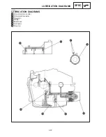
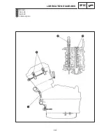
Page 46: ...2 24 1 2 LUBRICATION DIAGRAMS SPEC 1 Camshaft 2 Crankshaft ...
Page 54: ...SPEC ...
Page 55: ...CHK ADJ 3 ...
Page 57: ...CHK ADJ ...
Page 109: ...CHK ADJ ...
Page 110: ...ENG 4 ...
Page 189: ...COOL 5 ...
Page 191: ...COOL ...
Page 202: ...CARB 6 ...
Page 204: ...CARB ...
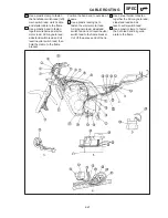
Page 216: ...6 12 CARB ...
Page 217: ...CHAS 7 ...
Page 288: ...ELEC 8 ...
Page 290: ...ELEC ...
Page 292: ...8 2 CIRCUIT DIAGRAM ELEC CIRCUIT DIAGRAM ...
Page 326: ...8 36 SIGNAL SYSTEM ELEC EB806000 SIGNAL SYSTEM CIRCUIT DIAGRAM ...
Page 355: ...TRBL SHTG 9 ...
Page 357: ...TRBL SHTG ...
Page 363: ...TRBL SHTG ...


