8-27
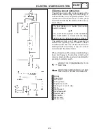
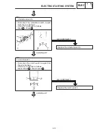
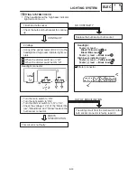
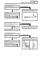
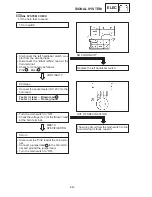
Stator coil resistance:
0.36
X
0.44
Ω
at 20
_
C
EB804011
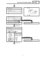
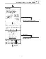
3. Charging voltage
S
Connect the engine tachometer to the spark
plug lead.
S
Connect the pocket tester (DC 20 V) to the
battery.
The charging circuit is not faulty.
Charging voltage = measured
voltage-terminal voltage:
0.2
X
2.5 V up
OUT OF
SPECIFICATION
MEETS SPECIFICATION
:
EB804012
:
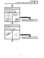
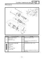
4. Stator coil resistance
S
Remove the generator cover.
S
Connect the pocket tester (
Ω
1) to the
stator coils.
Replace the stator coil assembly.
BOTH MEET
SPECIFICATION
OUT OF SPECIFICATION
Tester (+) lead
White terminal
Tester (–) lead
White terminal
Tester (+) lead
White terminal
Tester (–) lead
White terminal
S
Measure the stator coil resistance.
Tester (+) lead
Battery (+) terminal
Tester (–) lead
Battery (–) terminal
S
Measure the battery terminal voltage.
S
Start the engine and accelerate to about
5,000 r / min.
S
Check the terminal voltage.
1
2
1
3
NOTE:
Use a fully charged battery.
1
CHARGING SYSTEM
ELEC
Summary of Contents for 1998 FZS600 5DM1-AE1
Page 1: ......
Page 2: ......
Page 8: ......
Page 9: ...GEN INFO 1 ...
Page 11: ...GEN INFO ...
Page 20: ...SPEC 2 ...
Page 22: ...SPEC ...
Page 46: ...2 24 1 2 LUBRICATION DIAGRAMS SPEC 1 Camshaft 2 Crankshaft ...
Page 54: ...SPEC ...
Page 55: ...CHK ADJ 3 ...
Page 57: ...CHK ADJ ...
Page 109: ...CHK ADJ ...
Page 110: ...ENG 4 ...
Page 189: ...COOL 5 ...
Page 191: ...COOL ...
Page 202: ...CARB 6 ...
Page 204: ...CARB ...
Page 216: ...6 12 CARB ...
Page 217: ...CHAS 7 ...
Page 288: ...ELEC 8 ...
Page 290: ...ELEC ...
Page 292: ...8 2 CIRCUIT DIAGRAM ELEC CIRCUIT DIAGRAM ...
Page 326: ...8 36 SIGNAL SYSTEM ELEC EB806000 SIGNAL SYSTEM CIRCUIT DIAGRAM ...
Page 355: ...TRBL SHTG 9 ...
Page 357: ...TRBL SHTG ...
Page 363: ...TRBL SHTG ...

