4-62
CRANKSHAFT
ENG
2
b
a
b
a
CAUTION:
NOTE:
NOTE:
NOTE:
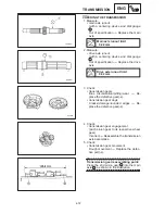
Crankshaft-journal-to-crank-
shaft-journal-bearing clearance
0.025
0.043 mm
Limit 0.08 mm
Do not interchange the crankshaft jour-
nal bearings. To obtain the correct crank-
shaft journal-to-crankshaft-journal-bear-
ing clearance and prevent engine
damage, the crankshaft journal bearings
must be installed in their original posi-
tion.
a. Clean the crankshaft journal bearings,
crankshaft journals, and bearing portions
of the crankcase.
b. Place the upper crankcase upside down
on a bench.
c. Install the crankshaft journal upper bear-
ings
1
and the crankshaft into the upper
crankcase.
Align the projections
a
of the crankshaft
journal upper bearings with the notches
b
in
the crankcase.
d. Put a piece of Plastigauge
2
on each
crankshaft journal.
Do not put the Plastigauge
over the oil hole
in the crankshaft journal.
e. Install the crankshaft journal lower bear-
ings into the lower crankcase and as-
semble the crankcase halves.
Align the projections
a
of the crankshaft
journal lower bearings with the notches
b
in the crankcase.
Do not move the crankshaft until the clear-
ance measurement has been completed.
Summary of Contents for 1998 FZS600 5DM1-AE1
Page 1: ......
Page 2: ......
Page 8: ......
Page 9: ...GEN INFO 1 ...
Page 11: ...GEN INFO ...
Page 20: ...SPEC 2 ...
Page 22: ...SPEC ...
Page 46: ...2 24 1 2 LUBRICATION DIAGRAMS SPEC 1 Camshaft 2 Crankshaft ...
Page 54: ...SPEC ...
Page 55: ...CHK ADJ 3 ...
Page 57: ...CHK ADJ ...
Page 109: ...CHK ADJ ...
Page 110: ...ENG 4 ...
Page 189: ...COOL 5 ...
Page 191: ...COOL ...
Page 202: ...CARB 6 ...
Page 204: ...CARB ...
Page 216: ...6 12 CARB ...
Page 217: ...CHAS 7 ...
Page 288: ...ELEC 8 ...
Page 290: ...ELEC ...
Page 292: ...8 2 CIRCUIT DIAGRAM ELEC CIRCUIT DIAGRAM ...
Page 326: ...8 36 SIGNAL SYSTEM ELEC EB806000 SIGNAL SYSTEM CIRCUIT DIAGRAM ...
Page 355: ...TRBL SHTG 9 ...
Page 357: ...TRBL SHTG ...
Page 363: ...TRBL SHTG ...


