7-51
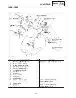
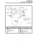
HANDLEBAR
CHAS
b
23 Nm (2.3 m
kg)
CAUTION:
NOTE:
NOTE:
NOTE:
NOTE:
EB704701
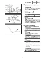
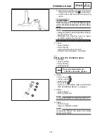
INSTALLING THE HANDLEBAR
1. Stand the motorcycle on a level surface.
Securely support the motorcycle so that
there is no danger of it falling over.
2. Install:
handlebar
1
upper handlebar holders
2
First, tighten the bolts on the front side
a
of the handlebar holder, then on the
rear side.
turn the handlebar all the way to the left
and right. If there is any contact with the
fuel tank, adjust the handlebar posi-
tion.
The upper handlebar holders should be
installed with the arrows facing forward.
Align the match marks
b
on the handlebar
with the upper surface of the lower handle-
bar holders.
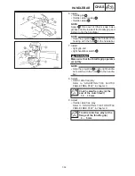
3. Install:
clutch lever holder
handlebar grip
1
left grip end
2
There should be 1.0 mm of clearance
a
be-
tween the handlebar grip and the left grip
end.
4. Install:
left handlebar switch
1
Align the projection
a
on the left handlebar
switch with the hole
b
in the handlebar.
5. Install:
master cylinder bracket
1
Align the mating surfaces of the master cyl-
inder bracket with the punch mark (right han-
dlebar switch side)
a
on the handlebar.
Summary of Contents for 1998 FZS600 5DM1-AE1
Page 1: ......
Page 2: ......
Page 8: ......
Page 9: ...GEN INFO 1 ...
Page 11: ...GEN INFO ...
Page 20: ...SPEC 2 ...
Page 22: ...SPEC ...
Page 46: ...2 24 1 2 LUBRICATION DIAGRAMS SPEC 1 Camshaft 2 Crankshaft ...
Page 54: ...SPEC ...
Page 55: ...CHK ADJ 3 ...
Page 57: ...CHK ADJ ...
Page 109: ...CHK ADJ ...
Page 110: ...ENG 4 ...
Page 189: ...COOL 5 ...
Page 191: ...COOL ...
Page 202: ...CARB 6 ...
Page 204: ...CARB ...
Page 216: ...6 12 CARB ...
Page 217: ...CHAS 7 ...
Page 288: ...ELEC 8 ...
Page 290: ...ELEC ...
Page 292: ...8 2 CIRCUIT DIAGRAM ELEC CIRCUIT DIAGRAM ...
Page 326: ...8 36 SIGNAL SYSTEM ELEC EB806000 SIGNAL SYSTEM CIRCUIT DIAGRAM ...
Page 355: ...TRBL SHTG 9 ...
Page 357: ...TRBL SHTG ...
Page 363: ...TRBL SHTG ...


