2-27
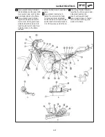
D Use a steel holder to fasten
together the AC magneto lead,
sidestand lead and oil
level / neutral switch lead.
E Use a plastic clamp to fasten
the horn lead and air guide
plate to the frame.
A Use a plastic clamp to fasten
the handlebar switch lead (left),
main switch lead, clutch cable
and starter cable to the frame.
B Use a plastic band to fasten
together wireharness, starter
motor lead, AC magneto lead,
sidestand switch lead and oil
level / neutral switch lead, then
hold the clamp to the frame
bracket.
CABLE ROUTING
SPEC
Position the band end to out side of
chassis.
C Use a plastic locking tie to
fasten the starter motor lead,
AC magneto lead, sidestand
switch lead and oil level / neutral
switch lead to the frame bracket.
Cut off the excess end of the tie.
Summary of Contents for 1998 FZS600 5DM1-AE1
Page 1: ......
Page 2: ......
Page 8: ......
Page 9: ...GEN INFO 1 ...
Page 11: ...GEN INFO ...
Page 20: ...SPEC 2 ...
Page 22: ...SPEC ...
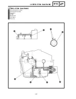
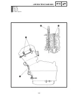
Page 46: ...2 24 1 2 LUBRICATION DIAGRAMS SPEC 1 Camshaft 2 Crankshaft ...
Page 54: ...SPEC ...
Page 55: ...CHK ADJ 3 ...
Page 57: ...CHK ADJ ...
Page 109: ...CHK ADJ ...
Page 110: ...ENG 4 ...
Page 189: ...COOL 5 ...
Page 191: ...COOL ...
Page 202: ...CARB 6 ...
Page 204: ...CARB ...
Page 216: ...6 12 CARB ...
Page 217: ...CHAS 7 ...
Page 288: ...ELEC 8 ...
Page 290: ...ELEC ...
Page 292: ...8 2 CIRCUIT DIAGRAM ELEC CIRCUIT DIAGRAM ...
Page 326: ...8 36 SIGNAL SYSTEM ELEC EB806000 SIGNAL SYSTEM CIRCUIT DIAGRAM ...
Page 355: ...TRBL SHTG 9 ...
Page 357: ...TRBL SHTG ...
Page 363: ...TRBL SHTG ...


