3-10
ADJUSTING THE VALVE CLEARANCE
CHK
ADJ
a
NOTE:
NOTE:
CAUTION:
NOTE:
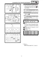
e. Install the new valve pad
1
and the valve
lifter
2
.
Apply molybdenum disulfide grease to the
valve pad.
Lubricate the valve lifter with molybdenum
disulfide oil.
The valve lifter must turn smoothly when
rotated by hand.
Install the valve lifter and the valve pad in
the correct place.
f. Install the exhaust and intake camshafts,
timing chain and camshaft caps.
Camshaft cap bolt
10 Nm (1.0 m
kg)
Refer to “CAMSHAFT” in chapter 4.
Lubricate the camshaft bearings, cam-
shaft lobes and camshaft journals.
First, install the exhaust camshaft.
Align the camshaft marks
a
with the cam-
shaft cap marks.
Rotate the crankshaft counterclockwise
several turns to seat the parts.
The camshaft caps must be tightened
evenly or damage to the cylinder head,
camshaft caps and camshafts will result.
g. Measure the valve clearance again.
h. If the valve clearance is still out of specifi-
cation, repeat all of the valve clearance
adjustment steps until the specified clear-
ance is obtained.
11. Install:
all removed parts
For installation, reverse the removal proce-
dure. Note the following points.
12. Install:
timing chain guide (exhaust side)
timing chain guide (upper)
timing chain tensioner
Refer to “CAMSHAFT” in CHAPTER 4.
13. Install:
AC magneto cover
Bolt (AC magneto cover):
12 Nm (1.2 m
kg)
Summary of Contents for 1998 FZS600 5DM1-AE1
Page 1: ......
Page 2: ......
Page 8: ......
Page 9: ...GEN INFO 1 ...
Page 11: ...GEN INFO ...
Page 20: ...SPEC 2 ...
Page 22: ...SPEC ...
Page 46: ...2 24 1 2 LUBRICATION DIAGRAMS SPEC 1 Camshaft 2 Crankshaft ...
Page 54: ...SPEC ...
Page 55: ...CHK ADJ 3 ...
Page 57: ...CHK ADJ ...
Page 109: ...CHK ADJ ...
Page 110: ...ENG 4 ...
Page 189: ...COOL 5 ...
Page 191: ...COOL ...
Page 202: ...CARB 6 ...
Page 204: ...CARB ...
Page 216: ...6 12 CARB ...
Page 217: ...CHAS 7 ...
Page 288: ...ELEC 8 ...
Page 290: ...ELEC ...
Page 292: ...8 2 CIRCUIT DIAGRAM ELEC CIRCUIT DIAGRAM ...
Page 326: ...8 36 SIGNAL SYSTEM ELEC EB806000 SIGNAL SYSTEM CIRCUIT DIAGRAM ...
Page 355: ...TRBL SHTG 9 ...
Page 357: ...TRBL SHTG ...
Page 363: ...TRBL SHTG ...


