3-7
ADJUSTING THE VALVE CLEARANCE
CHK
ADJ
NOTE:
NOTE:
7. Remove:
timing chain tensioner bolt
1
timing chain tensioner assembly
2
8. Remove:
timing chain guide
1
timing chain guide (upper)
2
camshaft cap
3
9. Remove:
camshaft
1
Refer to “DISASSEMBLING THE ENGINE
– CAMSHAFT AND CYLINDER HEAD” in
chapter 4.
When removing the timing chain and cam-
shafts, fasten a wire to the timing chain to
retrieve it if it falls into the crankcase.
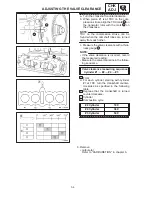
10. Adjust:
valve clearance
a. Remove the valve lifter
1
and the valve
pad
2
.
Cover the timing chain opening with a rag
to prevent the valve pad from falling into
the crankcase.
Make a note of the position of each valve
lifter
1
and valve pad
2
so that they can
be installed in the correct place.
b. Select the proper valve pad from the fol-
lowing table.
Valve pad
thickness range
Available valve
pads
Nos.
120
240
120
2.40 mm
25 thickness
in 0.05 mm
increments
Summary of Contents for 1998 FZS600 5DM1-AE1
Page 1: ......
Page 2: ......
Page 8: ......
Page 9: ...GEN INFO 1 ...
Page 11: ...GEN INFO ...
Page 20: ...SPEC 2 ...
Page 22: ...SPEC ...
Page 46: ...2 24 1 2 LUBRICATION DIAGRAMS SPEC 1 Camshaft 2 Crankshaft ...
Page 54: ...SPEC ...
Page 55: ...CHK ADJ 3 ...
Page 57: ...CHK ADJ ...
Page 109: ...CHK ADJ ...
Page 110: ...ENG 4 ...
Page 189: ...COOL 5 ...
Page 191: ...COOL ...
Page 202: ...CARB 6 ...
Page 204: ...CARB ...
Page 216: ...6 12 CARB ...
Page 217: ...CHAS 7 ...
Page 288: ...ELEC 8 ...
Page 290: ...ELEC ...
Page 292: ...8 2 CIRCUIT DIAGRAM ELEC CIRCUIT DIAGRAM ...
Page 326: ...8 36 SIGNAL SYSTEM ELEC EB806000 SIGNAL SYSTEM CIRCUIT DIAGRAM ...
Page 355: ...TRBL SHTG 9 ...
Page 357: ...TRBL SHTG ...
Page 363: ...TRBL SHTG ...


