5-4
10 Nm (1.0 m
kg)
Order
Job name / Part name
Q’ty
Remarks
1
2
3
4
5
6
7
8
9
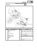
Removing the thermostat
Seat
Fuel tank
Drain the coolant
Thermo switch lead
(engine temperature)
Thermo switch lead (fan motor)
Reservoir tank hose
Carburetor inlet hose
Engine outlet hose
Engine outlet hose
Radiator inlet hose
Thermostat housing
Ground read
1
1
1
1
1
1
1
1
1
Remove the parts in the order listed.
Refer to “FRONT COWLING / SEAT /
SIDE COVER / FUEL TANK” section in
chapter 3.
Refer to “CHANGING THE COOLANT”
section in chapter 3.
Disconnect the lead.
Disconnect the coupler.
For installation, reverse the removal
procedure.
NOTE:
NOTE:
THERMOSTAT
COOL
THERMOSTAT
Summary of Contents for 1998 FZS600 5DM1-AE1
Page 1: ......
Page 2: ......
Page 8: ......
Page 9: ...GEN INFO 1 ...
Page 11: ...GEN INFO ...
Page 20: ...SPEC 2 ...
Page 22: ...SPEC ...
Page 46: ...2 24 1 2 LUBRICATION DIAGRAMS SPEC 1 Camshaft 2 Crankshaft ...
Page 54: ...SPEC ...
Page 55: ...CHK ADJ 3 ...
Page 57: ...CHK ADJ ...
Page 109: ...CHK ADJ ...
Page 110: ...ENG 4 ...
Page 189: ...COOL 5 ...
Page 191: ...COOL ...
Page 202: ...CARB 6 ...
Page 204: ...CARB ...
Page 216: ...6 12 CARB ...
Page 217: ...CHAS 7 ...
Page 288: ...ELEC 8 ...
Page 290: ...ELEC ...
Page 292: ...8 2 CIRCUIT DIAGRAM ELEC CIRCUIT DIAGRAM ...
Page 326: ...8 36 SIGNAL SYSTEM ELEC EB806000 SIGNAL SYSTEM CIRCUIT DIAGRAM ...
Page 355: ...TRBL SHTG 9 ...
Page 357: ...TRBL SHTG ...
Page 363: ...TRBL SHTG ...


