3-6
ADJUSTING THE VALVE CLEARANCE
CHK
ADJ
b
a
1
NOTE:
NOTE:
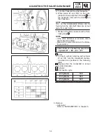
a. Turn the crankshaft counterclockwise.
b. When piston #1 is at TDC on the com-
pression stroke, align the TDC mark
a
on
the generator rotor with the mark
b
on
the crankcase.
TDC on the compression stroke can be
found when the camshaft lobes are turned
away from each other.
c. Measure the valve clearance with a thick-
ness gauge
1
.
S
If the valve clearance is incorrect, record
the measured reading.
S
Measure the valve clearance in the follow-
ing sequence.
Valve clearance measuring sequence
Cylinder #1
#2
#4
#3
A
Front
d. For each cylinder, starting with cylinder
#1 at TDC, turn the crankshaft counter-
clockwise as specified in the following
table.
B
Degrees that the crankshaft is turned
counterclockwise.
C
Cylinder
D
Combustion cycle
#2 Cylinder
180
_
#4 Cylinder
360
_
#3 Cylinder
540
_
6. Remove:
S
carburetor
Refer to “CARBURETION” in chapter 6.
Summary of Contents for 1998 FZS600 5DM1-AE1
Page 1: ......
Page 2: ......
Page 8: ......
Page 9: ...GEN INFO 1 ...
Page 11: ...GEN INFO ...
Page 20: ...SPEC 2 ...
Page 22: ...SPEC ...
Page 46: ...2 24 1 2 LUBRICATION DIAGRAMS SPEC 1 Camshaft 2 Crankshaft ...
Page 54: ...SPEC ...
Page 55: ...CHK ADJ 3 ...
Page 57: ...CHK ADJ ...
Page 109: ...CHK ADJ ...
Page 110: ...ENG 4 ...
Page 189: ...COOL 5 ...
Page 191: ...COOL ...
Page 202: ...CARB 6 ...
Page 204: ...CARB ...
Page 216: ...6 12 CARB ...
Page 217: ...CHAS 7 ...
Page 288: ...ELEC 8 ...
Page 290: ...ELEC ...
Page 292: ...8 2 CIRCUIT DIAGRAM ELEC CIRCUIT DIAGRAM ...
Page 326: ...8 36 SIGNAL SYSTEM ELEC EB806000 SIGNAL SYSTEM CIRCUIT DIAGRAM ...
Page 355: ...TRBL SHTG 9 ...
Page 357: ...TRBL SHTG ...
Page 363: ...TRBL SHTG ...


