4-12
4
6
5
3
2
1
“E”
“I”
C
C
CAMSHAFT
ENG
CAUTION:
NOTE:
CAUTION:
The camshaft cap bolts must be tight-
ened evenly or damage to the cylinder
head, camshaft caps, and camshafts will
result.
Camshaft cap bolt
10 Nm (1.0 m
kg)
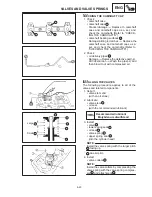
4. Install:
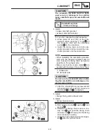
intake camshaft sprocket
exhaust camshaft sprocket
a. Turn the crankshaft counterclockwise.
b. When piston #1 is at TDC on the com-
pression stroke, align the “T” mark
a
on
the magneto rotor with the stationary
pointer
b
on the crankcase.
c. Install the timing chain onto both cam-
shaft sprockets and then install the cam-
shaft sprockets onto the camshafts.
When installing the camshaft sprockets,
start with the exhaust camshaft and be
sure to keep the timing chain as tight as
possible on the exhaust side.
Make sure that the match marks
c
are
parallel with the edge of the cylinder head.
“I”: Intake side
“E”: Exhaust side
Do not turn the crankshaft when instal-
ling the camshaft to avoid damage or im-
proper valve timing.
d. After the crankshaft is turned several full
turns and piston #1 is at TDC, make sure
that marks
a
and
b
are aligned.
5. Install:
timing chain guide (exhaust side)
6. Install:
timing chain tensioner
a. Remove the cap bolt
1
, washer
2
, and
springs
3
b. Release the timing chain tensioner one-
way cam
4
and push the timing chain
tensioner rod
5
all the way into the timing
chain tensioner housing.
c. Install the timing chain tensioner and gas-
ket
6
onto the cylinder block.
Summary of Contents for 1998 FZS600 5DM1-AE1
Page 1: ......
Page 2: ......
Page 8: ......
Page 9: ...GEN INFO 1 ...
Page 11: ...GEN INFO ...
Page 20: ...SPEC 2 ...
Page 22: ...SPEC ...
Page 46: ...2 24 1 2 LUBRICATION DIAGRAMS SPEC 1 Camshaft 2 Crankshaft ...
Page 54: ...SPEC ...
Page 55: ...CHK ADJ 3 ...
Page 57: ...CHK ADJ ...
Page 109: ...CHK ADJ ...
Page 110: ...ENG 4 ...
Page 189: ...COOL 5 ...
Page 191: ...COOL ...
Page 202: ...CARB 6 ...
Page 204: ...CARB ...
Page 216: ...6 12 CARB ...
Page 217: ...CHAS 7 ...
Page 288: ...ELEC 8 ...
Page 290: ...ELEC ...
Page 292: ...8 2 CIRCUIT DIAGRAM ELEC CIRCUIT DIAGRAM ...
Page 326: ...8 36 SIGNAL SYSTEM ELEC EB806000 SIGNAL SYSTEM CIRCUIT DIAGRAM ...
Page 355: ...TRBL SHTG 9 ...
Page 357: ...TRBL SHTG ...
Page 363: ...TRBL SHTG ...


