3-8
ADJUSTING THE VALVE CLEARANCE
CHK
ADJ
NOTE:
NOTE:
The thickness
a
of each valve pad is
marked in hundredths of millimeters on the
side that touches the valve lifter.
Since valve pads of various sizes are origi-
nally installed, the valve pad number must
be rounded in order to reach the closest
equivalent to the original.
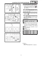
c. Round off the original valve pad number
according to the following table.
Last digit
Rounded valve
0 or 2
0
5
5
8
10
EXAMPLE:
Original valve pad number = 148 (thickness
= 1.48 mm)
Rounded value = 150
d. Locate the rounded number of the origi-
nal valve pad and the measured valve
clearance in the valve pad selection
table.
The point where the column and row in-
tersect is the new valve pad number.
The new valve pad number is only an
approximation. The valve clearance must be
measured again and the above steps should
be repeated if the measurement is still incor-
rect.
Summary of Contents for 1998 FZS600 5DM1-AE1
Page 1: ......
Page 2: ......
Page 8: ......
Page 9: ...GEN INFO 1 ...
Page 11: ...GEN INFO ...
Page 20: ...SPEC 2 ...
Page 22: ...SPEC ...
Page 46: ...2 24 1 2 LUBRICATION DIAGRAMS SPEC 1 Camshaft 2 Crankshaft ...
Page 54: ...SPEC ...
Page 55: ...CHK ADJ 3 ...
Page 57: ...CHK ADJ ...
Page 109: ...CHK ADJ ...
Page 110: ...ENG 4 ...
Page 189: ...COOL 5 ...
Page 191: ...COOL ...
Page 202: ...CARB 6 ...
Page 204: ...CARB ...
Page 216: ...6 12 CARB ...
Page 217: ...CHAS 7 ...
Page 288: ...ELEC 8 ...
Page 290: ...ELEC ...
Page 292: ...8 2 CIRCUIT DIAGRAM ELEC CIRCUIT DIAGRAM ...
Page 326: ...8 36 SIGNAL SYSTEM ELEC EB806000 SIGNAL SYSTEM CIRCUIT DIAGRAM ...
Page 355: ...TRBL SHTG 9 ...
Page 357: ...TRBL SHTG ...
Page 363: ...TRBL SHTG ...


