4-19
a
b
VALVES AND VALVE SPRINGS
ENG
a
b
NOTE:
NOTE:
EB403400
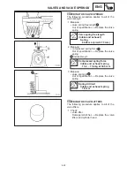
CHECKING THE VALVES AND VALVE
GUIDES
The following procedure applies to all of the
valves and valve guides.
1. Measure:
S
valve-stem-to-valve-guide clearance
Valve-stem-to-valve-guide
clearance =
Valve guide inside diameter
–
Valve stem diameter
Out of specification
Replace the valve
guide.
Valve-stem-to-valve-guide
clearance
Intake
Limit: 0.08 mm
Exhaust
Limit: 0.1 mm
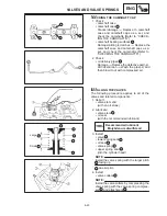
2. Replace:
S
valve guide
To ease valve guide removal and installa-
tion, and to maintain the correct fit, heat the
cylinder head to 100
_
C (212
_
C) in an oven.
a. Remove the valve guide with a valve
guide remover
1
.
b. Install the new valve guide with a valve
guide installer
2
and valve guide remov-
er
1
.
c. After installing the valve guide, bore the
valve guide with a valve guide reamer
3
to obtain the proper valve-stem-to-valve-
guide clearance.
After replacing the valve guide, reface the
valve seat.
Valve guide remover (ø4.0 mm)
90890-04111
Valve guide installer (ø4.0 mm)
90890-04112
Valve guide reamer (ø4.0 mm)
90890-04113
3. Eliminate:
S
carbon deposits
(from the valve face and valve seat)
Summary of Contents for 1998 FZS600 5DM1-AE1
Page 1: ......
Page 2: ......
Page 8: ......
Page 9: ...GEN INFO 1 ...
Page 11: ...GEN INFO ...
Page 20: ...SPEC 2 ...
Page 22: ...SPEC ...
Page 46: ...2 24 1 2 LUBRICATION DIAGRAMS SPEC 1 Camshaft 2 Crankshaft ...
Page 54: ...SPEC ...
Page 55: ...CHK ADJ 3 ...
Page 57: ...CHK ADJ ...
Page 109: ...CHK ADJ ...
Page 110: ...ENG 4 ...
Page 189: ...COOL 5 ...
Page 191: ...COOL ...
Page 202: ...CARB 6 ...
Page 204: ...CARB ...
Page 216: ...6 12 CARB ...
Page 217: ...CHAS 7 ...
Page 288: ...ELEC 8 ...
Page 290: ...ELEC ...
Page 292: ...8 2 CIRCUIT DIAGRAM ELEC CIRCUIT DIAGRAM ...
Page 326: ...8 36 SIGNAL SYSTEM ELEC EB806000 SIGNAL SYSTEM CIRCUIT DIAGRAM ...
Page 355: ...TRBL SHTG 9 ...
Page 357: ...TRBL SHTG ...
Page 363: ...TRBL SHTG ...


