3-14
a
b
a
b
ADJUSTING THE THROTTLE CABLE FREE PLAY
CHK
ADJ
NOTE:
NOTE:
a
b
NOTE:
a
b
EB303032
ADJUSTING THE THROTTLE CABLE FREE
PLAY
Prior to adjusting the throttle cable free play,
the engine idling speed and carburetor syn-
chronization should be adjusted properly.
1. Check:
throttle cable free play
a
Out of specification
Adjust.
Throttle cable free play (at the
flange of the throttle grip)
3
5 mm
2. Remove:
bracket
ignition coil
fuel pump
3. Adjust:
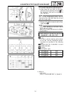
throttle cable free play
Carburetor side
When the motorcycle is accelerating,
throttle cable #1
1
is pulled and throttle
cable #2
2
is pushed.
a. Loosen the locknut
3
on throttle cable
#2.
b. Turn the adjuster
4
a
or
b
to take up
any slack on throttle cable #2.
c. Loosen the locknut
5
on throttle cable
#1.
d. Turn the adjuster
6
a
or
b
until the spe-
cified free play is obtained.
Direction
Throttle cable free play
is increased.
Direction
Throttle cable free play
is decreased.
e. Tighten the locknuts.
If the specified throttle cable free play cannot
be obtained on the carburetor side of the
cable, use the adjusting nut on the handle-
bar side.
Handlebar side
a. Loosen the locknut
1
.
b. Turn the adjusting nut
2
in direction
a
or
b
until the specified throttle cable free
play is obtained.
Direction
Throttle cable free play
is increased.
Direction
Throttle cable free play
is decreased.
c. Tighten the locknut.
Summary of Contents for 1998 FZS600 5DM1-AE1
Page 1: ......
Page 2: ......
Page 8: ......
Page 9: ...GEN INFO 1 ...
Page 11: ...GEN INFO ...
Page 20: ...SPEC 2 ...
Page 22: ...SPEC ...
Page 46: ...2 24 1 2 LUBRICATION DIAGRAMS SPEC 1 Camshaft 2 Crankshaft ...
Page 54: ...SPEC ...
Page 55: ...CHK ADJ 3 ...
Page 57: ...CHK ADJ ...
Page 109: ...CHK ADJ ...
Page 110: ...ENG 4 ...
Page 189: ...COOL 5 ...
Page 191: ...COOL ...
Page 202: ...CARB 6 ...
Page 204: ...CARB ...
Page 216: ...6 12 CARB ...
Page 217: ...CHAS 7 ...
Page 288: ...ELEC 8 ...
Page 290: ...ELEC ...
Page 292: ...8 2 CIRCUIT DIAGRAM ELEC CIRCUIT DIAGRAM ...
Page 326: ...8 36 SIGNAL SYSTEM ELEC EB806000 SIGNAL SYSTEM CIRCUIT DIAGRAM ...
Page 355: ...TRBL SHTG 9 ...
Page 357: ...TRBL SHTG ...
Page 363: ...TRBL SHTG ...


