8-54
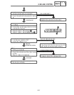
Les than 98
_
C
f
3*
105 to 98
_
C
S
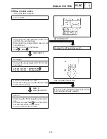
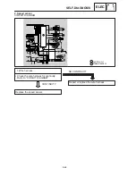
Remove the thermo switch from the thermo-
static valve housing.
S
Connect the pocket tester (
Ω
1) to the
thermo switch
.
S
Immerse the thermo switch in coolant
.
S
Check the thermo switch for continuity.
While heating the coolant use a thermome-
ter
to record the temperatures.
2
EB802017
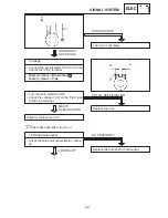
5. Thermo switch (fan, engine temperature)
:
Replace the thermo switch.
GOOD
CONDITION
BAD CONDITION
:
THERMO SWITCH “ON”
THERMO SWITCH “OFF”
1
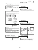
Handle the thermo switch with special care.
Never subjct it to strong shocks or allow it to
be dropped. Should it be dropped, it must be
replaced.
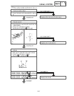
Tests 1 & 2; Heat-up tests
Tests 3* & 4*; Cool-down tests
f
: Continuity
: No continuity
A
B
Test
step
Good
condition
1
0
X
105
_
C
4*
f
2
More than 105
_
C
Water temperature
Thermo switch
98
_
C
105
_
C
3
COOLING SYSTEM
ELEC
Summary of Contents for 1998 FZS600 5DM1-AE1
Page 1: ......
Page 2: ......
Page 8: ......
Page 9: ...GEN INFO 1 ...
Page 11: ...GEN INFO ...
Page 20: ...SPEC 2 ...
Page 22: ...SPEC ...
Page 46: ...2 24 1 2 LUBRICATION DIAGRAMS SPEC 1 Camshaft 2 Crankshaft ...
Page 54: ...SPEC ...
Page 55: ...CHK ADJ 3 ...
Page 57: ...CHK ADJ ...
Page 109: ...CHK ADJ ...
Page 110: ...ENG 4 ...
Page 189: ...COOL 5 ...
Page 191: ...COOL ...
Page 202: ...CARB 6 ...
Page 204: ...CARB ...
Page 216: ...6 12 CARB ...
Page 217: ...CHAS 7 ...
Page 288: ...ELEC 8 ...
Page 290: ...ELEC ...
Page 292: ...8 2 CIRCUIT DIAGRAM ELEC CIRCUIT DIAGRAM ...
Page 326: ...8 36 SIGNAL SYSTEM ELEC EB806000 SIGNAL SYSTEM CIRCUIT DIAGRAM ...
Page 355: ...TRBL SHTG 9 ...
Page 357: ...TRBL SHTG ...
Page 363: ...TRBL SHTG ...

