2-5
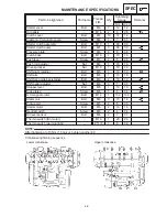
MAINTENANCE SPECIFICATIONS
SPEC
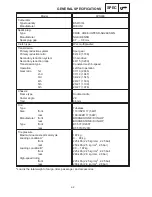
Item
Standard
Limit
Stem-to-guide clearance
IN
EX
Stem runout limit
Valve seat width
IN
EX
0.010
0.037 mm
0.025
0.052 mm
0.9
1.1 mm
0.9
1.1 mm
0.08 mm
0.1 mm
0.04 mm
1.6 mm
1.6 mm
Valve spring:
Free length
IN / EX
Set length (valve closed)
IN / EX
Compressed pressure
IN / EX
Tilt limit
IN / EX
Direction of winding
IN / EX
40.09 mm
34.5 mm
134
156 N (13.4
15.6 kg)
Clockwise
37.5 mm
2.5
/ 1.8 mm
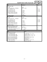
Piston:
Piston clearance
Piston size “D”
Measuring point “H”
Piston off-set
Piston off-set direction
Piston pin bore inside dia.
Piston pin outside dia.
0.025
0.050 mm
61.960
61.975 mm
5 mm
0.5 mm
In side
17.002
17.013 mm
16.991
17.000 mm
0.07 mm
Piston rings:
Top ring:
Type
Dimensions (B
T)
End gap (installed)
Side clearance (installed)
2nd ring:
Type
Dimensions (B
T)
End gap (installed)
Side clearance (installed)
Oil ring:
End gap (installed)
Barrel
0.8
2.2 mm
0.15
0.30 mm
0.020
0.075 mm
Taper
0.8
2.3 mm
0.25
0.40 mm
0.020
0.055 mm
1.5
2.3 mm
0.10
0.35 mm
0.6 mm
0.1 mm
0.7 mm
0.1 mm
Connecting rod:
Oil clearance
Color code (corresponding size)
0.043
0.066 mm
1. Blue 2. Black 3. Brown 4. Green
0.08 mm
Crankshaft:
Crankshaft width “A”
Assembly width “B”
Runout limit “C”
Big end side clearance “D”
Big end radial clearance “E”
Small end free play “F”
Journal oil clearance
Color code (corresponding size)
48.4 mm
296.8
298.0 mm
0.160
0.262 mm
0.043
0.066 mm
0.32
0.50 mm
0.025
0.043 mm
1. Black 2. Brown 3. Green 4. Yellow
5. Pink
0.03 mm
0.5 mm
0.08 mm
0.8 mm
0.08 mm
Summary of Contents for 1998 FZS600 5DM1-AE1
Page 1: ......
Page 2: ......
Page 8: ......
Page 9: ...GEN INFO 1 ...
Page 11: ...GEN INFO ...
Page 20: ...SPEC 2 ...
Page 22: ...SPEC ...
Page 46: ...2 24 1 2 LUBRICATION DIAGRAMS SPEC 1 Camshaft 2 Crankshaft ...
Page 54: ...SPEC ...
Page 55: ...CHK ADJ 3 ...
Page 57: ...CHK ADJ ...
Page 109: ...CHK ADJ ...
Page 110: ...ENG 4 ...
Page 189: ...COOL 5 ...
Page 191: ...COOL ...
Page 202: ...CARB 6 ...
Page 204: ...CARB ...
Page 216: ...6 12 CARB ...
Page 217: ...CHAS 7 ...
Page 288: ...ELEC 8 ...
Page 290: ...ELEC ...
Page 292: ...8 2 CIRCUIT DIAGRAM ELEC CIRCUIT DIAGRAM ...
Page 326: ...8 36 SIGNAL SYSTEM ELEC EB806000 SIGNAL SYSTEM CIRCUIT DIAGRAM ...
Page 355: ...TRBL SHTG 9 ...
Page 357: ...TRBL SHTG ...
Page 363: ...TRBL SHTG ...

