4-61
1
2
1
2
CRANKSHAFT
ENG
NOTE:
NOTE:
EB412110
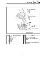
REMOVING THE CRANKSHAFT ASSEMBLY
1. Remove:
crankshaft assembly
1
crankshaft journal upper bearing
2
(from the upper crankcase)
timing chain guide (intake side)
Identify the position of each crankshaft jour-
nal upper bearing so that it can be reinstalled
in its original place.
EB412121
REMOVING THE CONNECTING RODS
1. Remove:
connecting rods
1
big end bearings
2
Identify the position of each big end bearing
so that it can be reinstalled in its original
place.
EB412401
CHECKING THE CRANKSHAFT AND
CONNECTING RODS
1. Measure:
crankshaft runout
Out of specification
Replace the crank-
shaft.
Crankshaft runout
Less than 0.03 mm
2. Check:
crankshaft journal surfaces
crankshaft pin surfaces
bearing surfaces
Scratches / wear
Replace the crank-
shaft.
3. Measure:
crankshaft-journal-to-crankshaft-journal-
bearing clearance
Out of specification
Replace the crank-
shaft journal bearings.
Summary of Contents for 1998 FZS600 5DM1-AE1
Page 1: ......
Page 2: ......
Page 8: ......
Page 9: ...GEN INFO 1 ...
Page 11: ...GEN INFO ...
Page 20: ...SPEC 2 ...
Page 22: ...SPEC ...
Page 46: ...2 24 1 2 LUBRICATION DIAGRAMS SPEC 1 Camshaft 2 Crankshaft ...
Page 54: ...SPEC ...
Page 55: ...CHK ADJ 3 ...
Page 57: ...CHK ADJ ...
Page 109: ...CHK ADJ ...
Page 110: ...ENG 4 ...
Page 189: ...COOL 5 ...
Page 191: ...COOL ...
Page 202: ...CARB 6 ...
Page 204: ...CARB ...
Page 216: ...6 12 CARB ...
Page 217: ...CHAS 7 ...
Page 288: ...ELEC 8 ...
Page 290: ...ELEC ...
Page 292: ...8 2 CIRCUIT DIAGRAM ELEC CIRCUIT DIAGRAM ...
Page 326: ...8 36 SIGNAL SYSTEM ELEC EB806000 SIGNAL SYSTEM CIRCUIT DIAGRAM ...
Page 355: ...TRBL SHTG 9 ...
Page 357: ...TRBL SHTG ...
Page 363: ...TRBL SHTG ...


