4-66
CRANKSHAFT
ENG
2
2
3
2
2
NOTE:
For example, if the connecting rod “P
1
” and
the crankshaft web “P1” numbers are “4”
and “1” respectively, then the bearing size
for “P
1
” is:
Bearing size for P
1
:
P
1
(connecting rod) – P1 (crankshaft-
web) = 4 – 1 = 3 (brown)
BIG END
BEARING
COLOR CODE
1
2
3
4
blue
black
brown green
EB412700
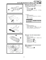
INSTALLING THE CONNECTING RODS
1. Lubricate:
bolt threads
nut seats
(with the recommended lubricant)
Recommended lubricant
Molybdenum disulfide grease
2. Lubricate:
crankshaft pins
big end bearings
connecting rod inner surface
(with the recommended lubricant)
Recommended lubricant
Engine oil
3. Install:
big end bearings
1
connecting rods
2
connecting rod caps
3
(onto the crankshaft pins)
Align the projections on the big end bear-
ings with the notches in the connecting
rods and connecting rod caps.
Be sure to reinstall each big end bearing in
its original place.
Make sure that the “Y” marks
a
on the
connecting rods face towards the left side
of the crankshaft.
Make sure that the characters on both the
connecting rod and connecting rod cap are
aligned.
Summary of Contents for 1998 FZS600 5DM1-AE1
Page 1: ......
Page 2: ......
Page 8: ......
Page 9: ...GEN INFO 1 ...
Page 11: ...GEN INFO ...
Page 20: ...SPEC 2 ...
Page 22: ...SPEC ...
Page 46: ...2 24 1 2 LUBRICATION DIAGRAMS SPEC 1 Camshaft 2 Crankshaft ...
Page 54: ...SPEC ...
Page 55: ...CHK ADJ 3 ...
Page 57: ...CHK ADJ ...
Page 109: ...CHK ADJ ...
Page 110: ...ENG 4 ...
Page 189: ...COOL 5 ...
Page 191: ...COOL ...
Page 202: ...CARB 6 ...
Page 204: ...CARB ...
Page 216: ...6 12 CARB ...
Page 217: ...CHAS 7 ...
Page 288: ...ELEC 8 ...
Page 290: ...ELEC ...
Page 292: ...8 2 CIRCUIT DIAGRAM ELEC CIRCUIT DIAGRAM ...
Page 326: ...8 36 SIGNAL SYSTEM ELEC EB806000 SIGNAL SYSTEM CIRCUIT DIAGRAM ...
Page 355: ...TRBL SHTG 9 ...
Page 357: ...TRBL SHTG ...
Page 363: ...TRBL SHTG ...

