4-15
CYLINDER HEAD
ENG
NOTE:
NOTE:
NOTE:
EB402101
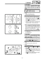
REMOVING THE CYLINDER HEADS
1. Remove:
cylinder head nuts
Loosen the nuts in the proper sequence as
shown.
Loosen each nut 1 / 2 of a turn at a time.
After all of the nuts are fully loosened, re-
move them.
EB402403
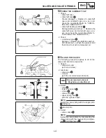
CHECKING THE CYLINDER HEADS
The following procedure applies to all of the cyl-
inder heads.
1. Eliminate:
carbon deposits
(from the combustion chambers with a
pounded scraper)
Do not use a sharp instument to avoid dam-
aging or scratching:
spark plug threads
valve seats
2. Check:
cylinder head
Damage / scratches
Replace.
cylinder head water jacket
Mineral deposits / rust
Eliminate.
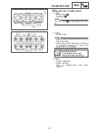
3. Measure:
cylinder head warpage
Out of specification
Resurface the cylin-
der head.
Cylinder head warpage
Less than 0.05 mm
a. Place a straightedge
1
and a thickness
gauge
2
across the cylinder head.
b. Measure the warpage.
c. If the limited is exceeded, resurface the
cylinder head as follows.
d. Place a 400
600 grit wet sandpaper on
the surface plate and resurface the cylin-
der head using a figure-eight sanding pat-
tern.
To ensure an even surface, rotate the cylin-
der head several times.
Summary of Contents for 1998 FZS600 5DM1-AE1
Page 1: ......
Page 2: ......
Page 8: ......
Page 9: ...GEN INFO 1 ...
Page 11: ...GEN INFO ...
Page 20: ...SPEC 2 ...
Page 22: ...SPEC ...
Page 46: ...2 24 1 2 LUBRICATION DIAGRAMS SPEC 1 Camshaft 2 Crankshaft ...
Page 54: ...SPEC ...
Page 55: ...CHK ADJ 3 ...
Page 57: ...CHK ADJ ...
Page 109: ...CHK ADJ ...
Page 110: ...ENG 4 ...
Page 189: ...COOL 5 ...
Page 191: ...COOL ...
Page 202: ...CARB 6 ...
Page 204: ...CARB ...
Page 216: ...6 12 CARB ...
Page 217: ...CHAS 7 ...
Page 288: ...ELEC 8 ...
Page 290: ...ELEC ...
Page 292: ...8 2 CIRCUIT DIAGRAM ELEC CIRCUIT DIAGRAM ...
Page 326: ...8 36 SIGNAL SYSTEM ELEC EB806000 SIGNAL SYSTEM CIRCUIT DIAGRAM ...
Page 355: ...TRBL SHTG 9 ...
Page 357: ...TRBL SHTG ...
Page 363: ...TRBL SHTG ...


