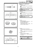
4-64
CRANKSHAFT
ENG
A
1
1
b
a
1
1
CAUTION:
NOTE:
For example, if the crankcase “J
1
” and
crankshaft web “J1” numbers are “6” and “2”
respectively, then the bearing size for “J1” is:
Bearing size for J1:
J
1
(crankcase) – J1 (crankshaft web) +
1 = 6 – 2 + 1 = 5 (yellow)
CRANKSHAFT
JOURNAL
BEARING
COLOR CODE 1
1
2
3
4
5
6
blue
black
brown
green yellow
pink
5. Measure:
crankshaft-pin-to-big-end-bearing clear-
ance
Out of specification
Replace the big end
bearings.
Crankshaft-pin-to-big-end-
bearing clearance
0.043
0.066 mm
Limit 0.08 mm
The following procedure applies to all of
the connecting rods.
Do not interchange the big end bearings
and connecting rods. To obtain the cor-
rect crankshaft-pin-to-big-end-bearing
clearance and prevent engine damage,
the big end bearings must be installed in
their original positions.
a. Clean the big end bearings, crankshaft
pins, and bearing portions of the connect-
ing rods.
b. Install the big end upper bearing into the
connecting rod and the big end lower
bearing into the connecting rod cap.
Align the projections
a
on the big end bear-
ings with the notches
b
in the connecting
rod and connecting rod cap.
c. Put a piece of Plastigauge
1
on the
crankshaft pin.
Summary of Contents for 1998 FZS600 5DM1-AE1
Page 1: ......
Page 2: ......
Page 8: ......
Page 9: ...GEN INFO 1 ...
Page 11: ...GEN INFO ...
Page 20: ...SPEC 2 ...
Page 22: ...SPEC ...
Page 46: ...2 24 1 2 LUBRICATION DIAGRAMS SPEC 1 Camshaft 2 Crankshaft ...
Page 54: ...SPEC ...
Page 55: ...CHK ADJ 3 ...
Page 57: ...CHK ADJ ...
Page 109: ...CHK ADJ ...
Page 110: ...ENG 4 ...
Page 189: ...COOL 5 ...
Page 191: ...COOL ...
Page 202: ...CARB 6 ...
Page 204: ...CARB ...
Page 216: ...6 12 CARB ...
Page 217: ...CHAS 7 ...
Page 288: ...ELEC 8 ...
Page 290: ...ELEC ...
Page 292: ...8 2 CIRCUIT DIAGRAM ELEC CIRCUIT DIAGRAM ...
Page 326: ...8 36 SIGNAL SYSTEM ELEC EB806000 SIGNAL SYSTEM CIRCUIT DIAGRAM ...
Page 355: ...TRBL SHTG 9 ...
Page 357: ...TRBL SHTG ...
Page 363: ...TRBL SHTG ...


