4-18
VALVES AND VALVE SPRINGS
ENG
1
a
NOTE:
NOTE:
NOTE:
NOTE:
EB403100
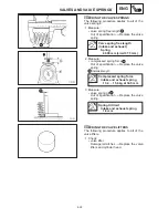
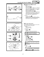
REMOVING THE VALVES
The following procedure applies to all of the
valves and related components.
Before removing the internal parts of the
cylinder head (e.g., valves, valve springs,
valve seats), make sure that the valves
properly seal.
1. Remove:
valve lifter
1
valve pad
Make a note of the position of each valve
lifter and valve pad so that they can be
reinstalled in their original place.
2. Check:
valve sealing
Leakage at the valve seat
Check the
valve face, valve seat, and valve seat
aidth.
Refer to “CHECKING THE VALVE
SEATS”.
a. Pour a clean solvent
a
into the intake
and exhaust ports.
b. Check that the valves properly seal.
There should be no leakage at the valve
seat
1
.
3. Remove:
valve cotters
1
Remove the valve cotters by compressing
the valve spring with the valve spring com-
pressor
2
and attachment
3
.
Valve spring compressor
90890-04019
Attachment
90890-04114
4. Remove:
upper spring seat
1
valve spring
2
oil seal
3
lower spring seat
4
valve
5
Identify the position of each part very care-
fully so that it can be reinstalled in its original
place.
Summary of Contents for 1998 FZS600 5DM1-AE1
Page 1: ......
Page 2: ......
Page 8: ......
Page 9: ...GEN INFO 1 ...
Page 11: ...GEN INFO ...
Page 20: ...SPEC 2 ...
Page 22: ...SPEC ...
Page 46: ...2 24 1 2 LUBRICATION DIAGRAMS SPEC 1 Camshaft 2 Crankshaft ...
Page 54: ...SPEC ...
Page 55: ...CHK ADJ 3 ...
Page 57: ...CHK ADJ ...
Page 109: ...CHK ADJ ...
Page 110: ...ENG 4 ...
Page 189: ...COOL 5 ...
Page 191: ...COOL ...
Page 202: ...CARB 6 ...
Page 204: ...CARB ...
Page 216: ...6 12 CARB ...
Page 217: ...CHAS 7 ...
Page 288: ...ELEC 8 ...
Page 290: ...ELEC ...
Page 292: ...8 2 CIRCUIT DIAGRAM ELEC CIRCUIT DIAGRAM ...
Page 326: ...8 36 SIGNAL SYSTEM ELEC EB806000 SIGNAL SYSTEM CIRCUIT DIAGRAM ...
Page 355: ...TRBL SHTG 9 ...
Page 357: ...TRBL SHTG ...
Page 363: ...TRBL SHTG ...

