4-25
10 Nm (1.0 m
kg)
Order
Job name / Part name
Q’ty
Remarks
1
2
3
4
5
6
7
8
9
10
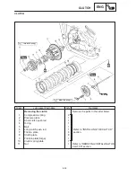
Removing the cylinder and pistons
Cylinder head
Water jacket joint
O-ring
Cylinder
Cylinder gasket
Dowel pin
O-ring
Piston pin circlip
Piston pin
Piston
Piston ring set
1
2
1
1
2
4
8
4
4
4
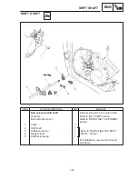
Remove the parts in the order listed.
Refer to “CYLINDER HEAD” section.
Refer to “INSTALLING THE PISTON AND
CYLINDER” section.
Refer to “REMOVING THE CYLINDER
AND PISTONS/ INSTALLING THE
PISTON AND CYLINDER” section.
For installation, reverse the removal
procedure.
CYLINDER AND PISTON
ENG
CYLINDER AND PISTON
Summary of Contents for 1998 FZS600 5DM1-AE1
Page 1: ......
Page 2: ......
Page 8: ......
Page 9: ...GEN INFO 1 ...
Page 11: ...GEN INFO ...
Page 20: ...SPEC 2 ...
Page 22: ...SPEC ...
Page 46: ...2 24 1 2 LUBRICATION DIAGRAMS SPEC 1 Camshaft 2 Crankshaft ...
Page 54: ...SPEC ...
Page 55: ...CHK ADJ 3 ...
Page 57: ...CHK ADJ ...
Page 109: ...CHK ADJ ...
Page 110: ...ENG 4 ...
Page 189: ...COOL 5 ...
Page 191: ...COOL ...
Page 202: ...CARB 6 ...
Page 204: ...CARB ...
Page 216: ...6 12 CARB ...
Page 217: ...CHAS 7 ...
Page 288: ...ELEC 8 ...
Page 290: ...ELEC ...
Page 292: ...8 2 CIRCUIT DIAGRAM ELEC CIRCUIT DIAGRAM ...
Page 326: ...8 36 SIGNAL SYSTEM ELEC EB806000 SIGNAL SYSTEM CIRCUIT DIAGRAM ...
Page 355: ...TRBL SHTG 9 ...
Page 357: ...TRBL SHTG ...
Page 363: ...TRBL SHTG ...


