Left Front Heat Sink Component
8-18
Force EZ-C Series Service Manual
Replace the Left Front Heat Sink Components.
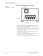
Figure 8-3.
Left front heat sink components
•
To replace the
HVPS (high voltage power supply) output resistor
, remove
the screw and washer that secure it to the heat sink. Position the new HVPS
output resistor on the heat sink and reinstall the washer and screw.
•
To replace one or more
HVPS (high voltage power supply) output diodes
,
remove the screw and washer that secure the diode to the heat sink. Position
the new diode on the heat sink and reinstall the washer and screw.
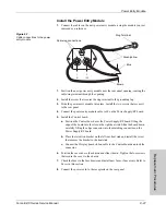
Install the Left Front Heat Sink
1.
Slide the left front heat sink component leads into the matching sockets on the
Power Supply/RF board.
2.
Install the two screws that secure the heat sink to the Power Supply/RF board.
3.
Position the cover above the chassis and slide it down. Tighten the four
screws that secure the cover to the chassis.
Notice
Calibrate the generator after you install a new heatsink or replace components on
the heat sink. Component differences may affect output waveforms. Refer to
Calibrating the Force EZ-C Series Electrosurgical Generator
in Section 6 for
instructions.
HVPS output diodes
HVPS output resistor


