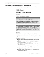
Correcting Integrated Circuit (IC) Malfunctions
T
roubleshooting
Force EZ-C Series Service Manual
7-23
5.
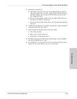
Reinstall the Control board.
a.
Position the Control board over the Power Supply/RF board, fitting the
edge of the board into the slot on the right heat sink. Slide the board down,
carefully fitting the edge connector into the matching connector on the
Power Supply/RF board.
b.
Place the retention bracket on the left rear heat sink and install the screw
that secures the bracket to the heat sink.
c.
Connect the Display board ribbon cable to the Control board and lock the
connector.
6.
Turn on the generator. If the generator successfully completes the self-test,
reinstall the cover (step 11).
7.
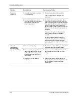
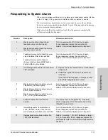
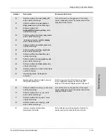
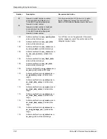
If the alarm number reappears, replace programmable IC U9.
a.
Turn off the generator.
b.
Remove the Control board (step 3).
c.
Grip IC U9 with the chip extractor and lift it out of its socket.
d.
Align the notch on the new chip above the notch on the socket and gently
press the chip into the socket.
e.
Reinstall the Control board (step 5).
8.
Turn on the generator. If the generator successfully completes the self-test,
reinstall the cover (step 11).
9.
If the alarm number reappears, replace the Control board.
a.
Turn off the generator.
b.
Remove the Control board (step 3).
c.
Install the new Control board (step 5).
10.
Calibrate the generator. Refer to Section 6 for instructions. If the alarm
number reappears, record the number and call the Valleylab Service Center.
11.
To reinstall the cover, position the cover above the chassis and slide it down.
Tighten the four screws that secure the cover to the chassis.


