Power Entry Module
Replacement Procedures
Force EZ-C Series Service Manual
8-27
Install the Power Entry Module
1.
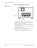
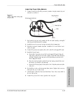
Connect the cables on the new power entry module, using the module you just
removed as a reference.
Figure 8-7.
Cable connections to the power
entry module
1.
Position the new power entry module near the rear panel opening, routing the
cable/ring terminal through the opening.
2.
Install the screw that secures the ring terminal to the grounding lug.
3.
Slide the power entry module into place. Install the two screws that secure it
to the rear panel.
4.
Connect the power entry module cable to J8 on the Power Supply/RF board.
5.
Install the Control board.
a.
Position the Control board over the Power Supply/RF board, fitting the
edge of the board into the slot on the right heat sink. Slide the board down,
carefully fitting the edge connector into the matching connector on the
Power Supply/RF board.
b.
Place the retention bracket on the left rear heat sink and install the screw
that secures the bracket to the heat sink.
c.
Connect the Display board ribbon cable to the Control board and lock the
connector.
6.
Position the cover above the chassis and slide it down. Tighten the four screws
that secure the cover to the chassis.
7.
Check the fuses in the fuse drawer and install new fuses, if necessary. Refer to
Fuses
in this section.
8.
Connect the power cord to the receptacle on the rear panel.
(L)
1
(N)
2
(G)
Ring Terminal
Green/yellow
Blue
Brown
Spare lug connections


